SSC JE 2012 Electrical question paper with Explained Solution | MES Electrical
Ques 1. The emf induced per phase in a three-phase star connected synchronous generator having the following data
Distribution factor = 0.955
Coil-span factor = 0.966
Frequency = 50 Hz
Flux per pole = 25 mwb
Turns per phase = 240, then emf per phase is
2128.36 Volts
1228.81 Volt✔
869.46 Volts
1737.80 Volts
E.M.F equation of an alternator is given as
E = Kc Kd √2π f Φ Np
Or E = 4.44 Kc Kd f Φ Np ………….. (since √2π = 4.44)
Where
Kc = Coil span factor
Kd = Distribution factor
Φ = Flux per pole
f = frequency
Np = Turns per phase
E = 4.44 × 0.955 × 0.966 × 50 × 25 × 10-3 × 240
E = 1228.1 volts
Ques 2. In a 1-phase transformer, the copper loss at full load is 600 watts. A half of the full load the copper loss will be
150 watts✔
75 watts
600 watts
300 watts
Copper loss is proportional to the square of load current. At half load, load current becomes half as voltage remains same, so the copper loss will become (1/2)2 i.e 1/4 times of full load copper loss.
So (Pcu)full load = 600 watts
(Pcu) half load = 600/4 = 150 watts
Ques 3. An autotransformer used with sodium vapour lamp should have high
Winding resistance
Leakage Reactance of winding✔
VA rating
Transformation Ratio
A sodium vapor lamp is also called the cold-cathode low-pressure lamp which gives high luminous output about three times higher than the other lamp.
For starting discharge through the lamp, it is essential that the striking voltage should be higher than the normal working voltage of the lamp. This high voltage is taken from a high reactance transformer or auto-transformer which has poor voltage regulation. Thus when discharge in the lamp takes place, the lamp current increase due to the decrease in the resistance of the gas in the tube and output voltages of the auto-transformer fall. The lamp then continues to operate normally.
Ques 4. In an auto-transformer, the number of turns in primary winding is 210 and in the secondary winding is 140. If the input current is 60 A, the current in output and in common winding are respectively.
40 A, 20A
40A, 100 A
90A, 30 A✔
90A, 150A
Auto-transformer ratio is given as
I1/I2 = N2/N1
60/I2 = 140/210
I2 = 90A
Current in common Winding Ic
Ic = (N2 – N1)I1/N2
= 60 x (210 – 140)/140
= 30 A
Ques 5. A 3-phase transformer has its primary connected in delta and secondary in star. The secondary to primary turns ratio per phase is 6. For a primary voltage of 200 V, the secondary voltage would be
2078 V✔
693 V
1200 V
58 V
Transformer ratio is given by
N1/N2 = V1/V2
0r N2/N1 = V2/V1
6/1 = V2/200
V2 = 1200 volt per phase
For star connection line voltage is
VL = √3 x 1200 = 2078.46 V
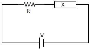
Ques 6. A resistance and another circuit element are connected in series across a dc voltage V. The voltage and zero after time. The other element is pure
Capacitance
Both (a) and (c)
Resistance
Inductance✔
Why inductor behaves as short circuit for DC voltage?
An inductor has a reactance equivalent XL = 2πfL. Since a DC supply will have frequency = 0, the reactance is 0 and the inductor would be short.
Detail explanation
Imagine a circuit of three elements in series – an input voltage source, inductor, and resistive load. The input source has been producing some constant (DC) voltage; If an inductor is connected with a DC source, it will not act as an inductor but acts like a simple resistor. The current through it will depend on the resistance of the inductor. Now increase the input voltage to a higher value.
The inductor immediately converts the voltage change to an equivalent “antivoltage” and applies it contrary to the input voltage change, the voltage “produced” by the inductor “jumps” with a magnitude equal to the input voltage change. Thus we have two voltage sources (an “original” and “cloned”:) contrary connected in series and neutralizing each other; as a result, the total (effective) voltage and accordingly the current do not change. After that, the current will increase exponentially (1 – e-t) and reach a constant value. The current will be maximum and the inductor will behave like a short circuit.
Ques 7. For RLC series resonance the current is
Minimum at leading P.F
Minimum at Lagging P.F
Maximum at unity P.F
Maximum at leading P.F✔
The total impedance of the series LCR circuit is given as
Z = R + j (X1 – X²)
where X1 is inductive reactance
and X2 is capacitive reactance.
At a particular frequency (resonant frequency), we find that X1=X2 because the resonance of a series RLC circuit occurs when the inductive and capacitive reactances are equal in magnitude but cancel each other because they are 180 degrees apart in phase. Therefore, the phase angle between voltage and current is zero and the power factor is unity.
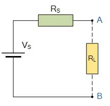
Ques 10. Application of Thevenin’s theorem in a circuit results in
An ideal voltage source
An ideal current source
A current source and an impedance in parallel
A voltage source and an impedance in series✔
The Thevenin equivalent resistance Rs is viewed from the open terminals A and B is given as. As per the Thevenin theorem, when resistance RL is connected across terminals A and B, the network behaves as a source of voltage Vs and internal resistance RT and this is called Thevenin equivalent circuit.


Qno 7 should be anwer is maximum at unity power factor
Sir sail ka previous year provide kijiye na