Ques 91. Excessive sparking at the brushes may be caused due to
Unequal Space
Dirt in commutator
Overload
All of the above
Answer.4All of the above
Explanation:-
Commutators and brush assemblies are a source of trouble in dc rotating machine. The continuous sliding of the brushes against the commutator wears the brushes down and tends to push them out of alignment causing bad contact between the commutator and brushes. When something does go wrong in commutation, it may be accompanied by excessive sparking, which aggravates the original trouble at once. When corm commutation is taking place, there will be very little sparking.
For satisfactory commutation of dc machines, a continuous contact must be maintained between commutator and brushes. The commutator must be mechanically true, the unit in good balance and the brushes should be in good shape and well adjusted.
Excessive sparking can be caused by a number of external factors, such as shorted or open armature windings, overload, and improper field strength.
There can be many reasons For sparking at the brushes in a DC motor.
Brush holder is not equally spaced:- this condition appears as the unequal sparking on different holders.
Holder is too far from commutator surface– If the holder is too far from the commutator surface it may fail to support the brush properly
Overload:- Overload. Overloading of the starter will cause high currents in the brushes, resulting in overheating and burning. Overloading is usually encountered when the starter is run for Periods long than 30 seconds
Dirty commutator: Oils, greases, and water will foul the commutator and cause excessive sparking between the commutator and the brushes, thus causing high temperatures
When there is excessive sparking at the commutator than good commutation cannot be obtained, the commutator and brush assembly must be checked, and any defect corrected as soon as possible. The inspection procedure and the steps taken to eliminate troubles are as follows:
Watch the machine operating to see if you can spot any arcing or excessive sparking elsewhere that might indicate a loose connection.
Check the brush positions to be sure that the brushes are commutating at the proper point (neutral plane).
Inspect all connections and make sure that none are loose.
Check the relative position of the brushes on the commutator. If they are unequally spaced, look for a bent brush holder.
Check the condition of the brushes. If they are badly worn, they should be replaced. When removing a brush, first lift the spring lever to release the pressure, then remove brush. Insert a new brush, making sure that it can move freely in the holder.
Check the commutator for dirt, pitting, irregularities, etc. Dirt can be removed with a piece of light canvas. Fine sandpaper will remove slight roughness. Never use emery cloth on a commutator.
Badly worn commutator should be skimmed on a lathe. This refers to machining away the irregularities of the surface.
Ques 92. Excessive motor vibration is caused by
Too much brush tension
Worn bearings
Open armature coil
Bent shaft
Answer 2.Worn Bearing
Explanation:-
Machine Vibration Causes
Almost all machine vibration is due to one or more of these causes
Repeating forces
Looseness
Resonance
Repeating forces
Repeating forces in machines are mostly due to the rotation of imbalanced, misaligned, worn, or improperly driven machine components.
Imbalance machine components:- Imbalance machine components contain “heavy spots,” which, when rotating, exert a repeating force on the machine. Imbalance is often caused by machining errors, nonuniform material density, variations in bolt sizes, air cavities in cast parts, missing balance weights, incorrect balancing, uneven electric motor windings, and broken, deformed, corroded or dirty fan blades or dirt that has dropped from a fan blade, suddenly creating a big imbalance.
Misaligned machine components:- It creates “bending moments,” which, when rotated, exert c repeating force on the machine. Misalignment is often caused by inaccurate assembly uneven floors, thermal expansion, distortions due to fastening torque, and improper mounting of couplings.
Worn machine:- Worncomponents exert a repeating force on the machine because of the rubbing of uneven worn surfaces. The wear in roller bearings, gears, and belts is often due to improper mounting, poor lubrication, manufacturing defects, and overloading.
Improperly driven machine components exert a repeating force on the machine because of intermittent power use. Examples include pumps receiving air in pulses, internal combustion engines with misfiring cylinders, and intermittent brush-commutator contact in DC motors.
Looseness
The looseness of machine parts causes a machine to vibrate. If parts become loose, the vibration that is normally at tolerable levels may become unrestrained and excessive. Looseness can cause vibration in both rotating and non rotating machinery. Looseness is often due to excessive bearing clearances, loose mounting bolts, mismatched parts, corrosion, and cracked structure.
Resonance
Resonance is a state of operation wherein an excitation frequency is close to a natural frequency of the machine structure, at this frequency, the damping of the vibration is very low and the result is resonance. When resonance occurs, the resulting vibration levels can be very high and can cause damage very quickly.
Ques 93. Two series motors are mechanically coupled. One machine is run as a motor and the other as a generator. The iron and friction losses of the machines will be identical when
Their speeds are identical
Their speeds and excitations are identical
Their speeds are equal and back e.m.f. are half the supply voltage.
Their ratings and armature sizes are equal
Answer.2.Their speeds and excitations are identical
Explanation:-
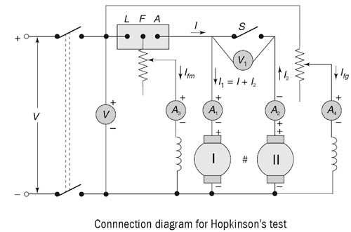
Hopkinson’s Test
Hopkinson’s test is also referred as the regenerative or Back-to-Back test.
When large machines are to be tested, the direct loading method involves a lot of loss of power. To avoid this, the regenerative method of testing is used where possible. This type of test can easily be performed on two identically shunt machines mechanically coupled to each other. One of the machines is run as a motor driving, the other machine as a generator. This generator supplies the motor. i.e. connected back to back so that most of the power required by the motor is fed from the generator, while the losses of both the machines — generator and motor — are supplied from the mains. This reduces the power taken from the mains. This type of test is known as Hopkinson test. Figure. shows the connection diagram for the Hopkinson test on two similar shunt machines.
One of the machines is started as the motor through the starter taking supply from the mains. The field current is adjusted to run the machine at the rated speed. The second machine is mechanically coupled and runs at the same speed. The excitation of the machine is so adjusted that the voltage across the armature is slightly higher than the supply voltage. This can be checked by the voltmeter V. The polarities of the machines should be suitable for parallel operation. When the voltmeter reads zero or slightly higher by 1 or 2 V, indicating that it would be generator action, the switch is closed so that both the machines are now in parallel across the supply. The excitation of the generator is so adjusted that the emf in the generator armature increases allowing more current through the motor armature and, thus, loading the machines. The losses are supplied by the mains. As two machines are similar and of equal size, and rating the constant losses — friction, windage.iron are assumed to be equal.
The field current of the generator is supplied from the mains. As an alternative, it can be supplied from the terminals of the generator. The location of the ammeter is such that it reads current I excluding the field currents of both the machines. The machine with smaller excitation current acts as a motor because back emf is less than that of induced emf of the other machine. Thus, it admits more armature current and develops greater torque. The load on the machines can be adjusted as desired and readings are taken.
Advantages of Hopkinson’s Test
The merits of this test are…
This test requires very small power compared to the full-load power of the motor-generator coupled system. That is why it is economical. Large machines can be tested at rated load without much power consumption.
Temperature rise and commutation can be observed and maintained in the limit because this test is done under full load condition.
Change in iron loss due to flux distortion can be taken into account due to the advantage of its full load condition.
Efficiency at different loads can be determined.
Disadvantages of Hopkinson’s Test
The demerits of this test are
It is difficult to find two identical machines needed for Hopkinson’s test.
Both machines cannot be loaded equally all the time.
Since the two machines are not loaded equally, therefore, the effect of armature reaction is not the same.
Due to the difference in the excitation, It is not possible to get separate iron losses for the two machines.
It is difficult to operate the machines at rated speed because field currents vary widely.
Ques 94. A DC shunt motor is running at 1200 RPM when excited with 220 V dc. Neglecting the losses and voltage dropped of the motor when connected to a 175 V supply is:
70 RPM
900 RPM
1050 RPM
1200 RPM
Answer.4.1200 RPM
Explanation:-
Extracting the data from given problem: Speed of DC shunt motor is 1200 rpm, the excitation voltage is 220V. The new excitation voltage is given as 175 V DC. In a DC shunt motor, the field current is given as
The flux of DC motor is φ = K’V. Where K is the constant based on armature design Now the losses and voltage drop is neglected therefore Voltage is also equal to back emf
V = Eb = KφN
N = V/Kφ = V/KK’V = 1/KK’
Now, it is observed that speed is constant and independent of voltage. Therefore, the value of voltage is 1200 rpm.
Ques 95. A d.c. shunt motor runs at 500 r.p.m. at 220 V. A resistance of 4.5 Ω is added in series with the armature for speed control. The armature resistance is 0.5 Ω. The current to stall the motor is
44 A
50 A
40 A
30 A
Answer.1.44 A
Explanation:-
As we know that back EMF of DC motor is directly proportional to the flux and speed.
Eb ∝ Nφ Eb ∝ N (φ is constant)
We can stall the motor (i.e., reduce its speed to zero) by putting more and more load on the shaft. When the motor is stalled since N = 0 therefore Eb = 0
From the voltage equation, the back EMF of DC motor at no-load
Eb = V − IaRa
Since external resistance, Rext is added in series with the motor. Hence
Eb = V − Ia(Ra + Rext)
0 = 220 − Ia(4.5 + 0.5)
Ia = 220 ⁄ 5
Ia = 44 A
Ques 96. A 240v dc shunt motor with an armature resistance of 0.5 has a full load current of 40A. Find out the ratio of the stalling torque to the full load torque when a resistance of 1 ohm is connected in series with the armature
12
6
4
10
Answer C.4
Explanation:-
Stalling torque is the torque at which speed would fall to zero.
With N = 0 , Eb = 0
Hence the value of armature current
From the voltage equation, the back EMF of DC motor at no-load
Eb = V − IaRa
Since external resistance, Rext is added in series with the motor. Hence
Eb = V − Ia(Ra + Rext)
0 = 240 − Ia(0.5 + 1)
Ia = 220 ⁄ 1.5
Ia = 160 A
The torque developed by a d.c motor is directly proportional to Flux per pole × Armature Resistance i.e
T ∝ ΦIa (Now flux is constant hence )
T ∝ Ia
Hence Ratio of stalling torque to full load torque will be
T2 ⁄ T1 = I2 ⁄ I1
T2 ⁄ T1 = 160/40 = 4
T2 ⁄ T1 = 4
Ques 97. If the applied voltage of a DC motor is 230 V, then back emf, for maximum power developed is
460 V
230 V
200 V
115 V
Answer. 4.115 V
Explanation:-
For maximum power output, the back emf is equal to half of the applied voltage.
Hence, Eb = V/2 = 230/2 ⇒115 V. where V is the terminal voltage.
or
For maximum power transfer load resistance should be same as series field resistance. So applied voltage 230 V will be divided equally 115 V on each section i.e. series field resistance and load resistance. Hence for maximum power development back emf should be 115 V.
Ques 98. In DC compound Motor the shunt field and series field winding is made up of _________ & ____________ respectively
High Resistance, Low Resistance
Low Resistance, High Resistance
Equal Resistance
None of the above
Answer 1.High Resistance, Low Resistance
Explanation:-
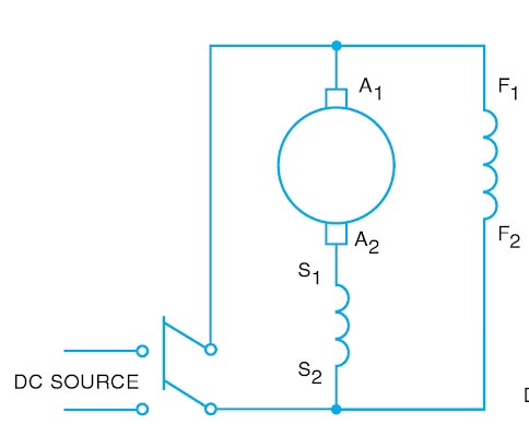
In a compound machine, there are two field windings, namely a shunt-field winding and a series-field winding. The shunt-field winding is connected in parallel with the armature and the series-field winding is connected in series with the combinations as shown in Fig.
The series winding will carry a large armature current Ia or IL, and therefore it is made of wires of large cross-section and has a few turns only. The resistance of a series winding is very small.
The shunt-winding is made up of wires of small cross-sections and has high resistance. Since the resistance of the shunt-field winding is high, the current flowing through it is small in comparison with the machine’s armature current. The main flux is created by the shunt winding but it is modified by the flux of the series winding. A compound machine, therefore, combines the best features of shunt machines and series machines
Ques 99. A DC Motor is driving a constant load torque having armature resistance of 0.15 Ω and armature current of 0.25 A having connected to a voltage of 230 V. Now a resistance of 1 ohm is added into the armature circuit. The ratio of their speed will be
0.25
1.24
0.62
0.72
Answer 4.0.72
Explanation:-
For a constant torque load, changing the armature resistance will not change the armature current. So, when the external resistance is added the speed of the motor decreases.
From the voltage equation, the back EMF of DC motor is
Eb1 = V − IaRa
= 230 − 0.25 × 60
Eb1 = 215
When the resistance of 1Ω is added in the armature circuit the new back EMF voltage
Eb2 = V − Ia(Ra + Rext)
= 240 − 60(0.25 + 1)
230 − 1.25 × 60
Eb2 = 155 V
Let the on load speed be N. As we know that back EMF of DC motor is directly proportional to the flux and speed.
Ques 100. A 240 V, dc shunt motor draws 15 A while supplying the rated load at a speed of 80 rad/s. The armature resistance is 0.5 Ω and the field winding resistance is 80 Ω. The external resistance to be added in the armature circuit to limit the armature current to 125% of its rated value is
31.9 Ω
31.1 Ω
15.9 Ω
15.1 Ω
Answer 2.31.1Ω
Explanation:-
Given Data:-
Supply Voltage V = 240 V Line Current IL = 15 A Shunt Resistance Rsh= 80Ω Armature Resistance Ra = 0.5 Ω Armature Current Ia =? Back EMF Eb =?
(i) Armature current
The Line current of DC shunt motor is the sum of Armature current and Shunt field current
IL = Ia + Ish
And Shunt Field Resistance is given as
Ish = V/Rsh = 240/80 = 3 A
∴ Ia = IL − Ish
Ia = 15 − 3 = 12A
Back EMF
From the voltage equation, the Back EMF of DC Motor is given by
Eb = V − IaRa
= 240 − 12 × 0.5 = 240 − 6
Eb = 234 V
External resistance to be added in the armature circuit to limit the armature current upto 125%.


An excellent questions and answers good luck sir
excellent
Superb 👍
Thank you 😊
Good work.