Ques 11. Ripple in the output current of a step-down chopper feeding RLE load is maximum when the duty cycle is equal to:
1
0.5✓
0.75
0.33
Chopper is a static device. A variable dc voltage is obtained from a constant dc voltage source. It is also known as the dc-to-dc converter. Chopper is widely used for motor control and regenerative braking.
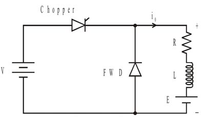
In a step-down chopper output voltage is less than the input voltage. Now consider the Fig of RLE step-down Chopper, where E signifies the Back EMF of the motor.
The thyristor in the circuit acts as a switch.
The Operation of the chopper can be divided into two modes.
During Mode 1 When the thyristor is conducting i.e chopper is ON, the supply is connected across the load. Current flows from supply to load.
During Mode 2 when the chopper is OFF, load current continues to flow in the same direction through FWD due to energy stored in inductor ‘L.
Load current can be continuous or discontinuous depending on the values of ‘L’ and duty cycle d.
For a continuous current operation, load current varies between two limits Imax and Imin.
During mode 1 the load current increase from the Imin to Imax.
During Mode 2 the load current decreased from Imax to Imin,
When current becomes equal to Imax the chopper is turned off and it is turned on when current reduces to Imin.
In Chopper the ripple (α) increases and reaches the maximum value at 50% duty cycle then again starts decreasing.
Note:- The expression of ripple and duty cycle is not included here and will be discussed in the theoretical section.
Ques 12. Which of the following are constant losses in Transformers?
Copper Losses(or I2R losses and Ohmic Losses) In the primary and secondary Winding. The copper Loss (Pc) has two components
Primary Winding copper losses
Secondary winding copper losses
Iron losses (or core Losses): Iron losses is called constant losses. The Iron Loss is further divided into two-part.
Hysteresis Losses
Eddy current Losses
Hysteresis loss is due to the reversal of magnetization in the transformer core. This loss depends upon the volume and grade of the iron, frequency of magnetic reversals, and value of flux density. It can be given by, the Steinmetz formula:
Hysteresis Loss = Kh × BM1.67 × f × v watts
where Kh = Hysteresis constant depends upon the material Bm = Maximum flux density f = frequency v = Volume of the core
Eddy current loss: In a transformer, the alternating current in the primary produces alternating flux in the core, this flux links with the secondary of the transformer and induces emf in the secondary, it may be possible that flux also links with some other conducting parts of transformer such as ferromagnetic core or iron body and induces local emf in these parts of transformer which will cause a circulating current to flow in these parts causing heat loss. These currents are called eddy currents and this loss is called eddy current loss.
Eddy current losses in the transformer is given by
Eddy current losses = Ke × Bm2 × f2 × t2
Where Ke = Eddy’s current constant t = thickness of the core
From the above discussion, we can say that the Hysteresis loss depends upon both voltage and frequency, while the eddy current loss mainly depends upon voltage.
As for transformers, normally we keep the supply voltage and frequency constant in regards to maintaining stability and reliability. So, the iron losses also remain constant.
Ques 13. Deep bar rotor construction is used in three-phase induction motors to mainly:
Control Speed
Control Power Factor
Increase the Starting Torque✓
None of these
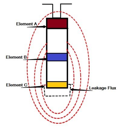
There is no constructional difference between the stator of the deep bar motor and that of an ordinary induction motor. The rotor consists of deep bars, short-circuited by two end rings one on each side. A bar may be assumed to be made up of a number of narrow layers connected in parallel. It is seen that the topmost layer element is linked with minimum leakage flux and therefore its leakage inductance is minimum. On the other hand, the bottom layer links maximum flux, therefore its leakage inductance is maximum.
At starting the rotor frequency is equal to the supply frequency. The bottom layer element offers more impedance to the current flow the upper layer hence the maximum current flows through the top layer and the minimum through the bottom layer. This unequal current distribution causes the effective rotor resistance to increase. With a high rotor resistance at starting condition, the starting torque is relatively high & starting current is low as desired.
Now under normal operating conditions, the slip and the rotor frequency are very small. The reactance of all the layers is small compared to their resistances. The impedances of all the layers are nearly equal, so current flows through all the parts of the bar equally. The resulting large cross-section area makes rotor resistance small, resulting in good efficiency at low slips.
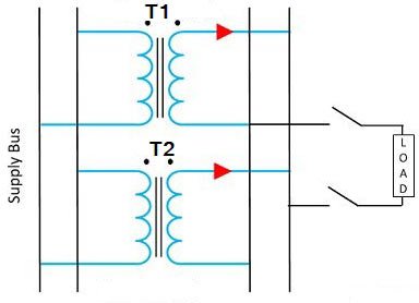
Ques 14. Two transformers with identical voltage ratings are working in parallel to supply a common load. The percentage impedance of one transformer is higher compared to that of other. The load sharing between the two transformers will:
Be proportional to their percentage impedance
Be independent of their percentage impedance
Be inversely proportional to their respective impedance✓
Depend on the resistance to leakage reactance ratio of each transformer
If two transformers are connected in parallel with similar per-unit impedances they will mostly share the load in the ratio of their KVA ratings. Here Load is mostly equal because it is possible to have two transformers with equal per-unit impedances but different X/R ratios. In this case, the line current will be less than the sum of the transformer currents and the combined capacity will be reduced accordingly.
A difference in the ratio of the reactance value to the resistance value of the per-unit impedance results in a different phase angle of the currents carried by the two paralleled transformers; one transformer will be working with a higher power factor and the other with a lower power factor than that of the combined output. Hence, the real power will not be proportionally shared by the transformers.
The current shared by two transformers running in parallel should be proportional to their MVA ratings.
The current carried by these transformers is inversely proportional to their internal impedance.
From the above two statements, it is clear that the current carried by these transformers is inversely proportional to their internal impedance. Hence the impedance of the transformer running in parallel is inversely proportional to their MVA rating.
Consider two transformers whose ratings are in the ratio of 4: 1. It is obvious that the first transformer must have one-fourth of the impedance of the second transformer hence the current drawn by the first transformer will be 4 times of the second transformer.
Hence if the percentage impedance of one transformer is higher compared to that of other. The load sharing between the two transformers will be inversely proportional to their respective impedance
Ques 15. The number of comparators required for an 8-bit flash ADC is:
8
255✓
16
256
The number of comparators requires in 8-Bit flash ADC for n bit resolution is given as
Number of comparator = 2n − 1
= 28 − 1
= 256 -1 = 255
Ques 16. A 35 V dc supply is connected across a resistance of 600 ohms in series with an unknown resistance R. A voltmeter having a resistance of 1.2 kΩ is connected across 600-ohm resistances and reads 5 V. The value of resistance R shall be:
1.2 kΩ
2.4 kΩ✓
120 kΩ
400 kΩ
From the following data, the fig is shown below
The voltmeter shows 5V which means it shows voltage drop across 600 ohm Resistance along with its internal Resistance, the parallel combination of resistance would be, (let it be R1)
R1=600 ||1200
R1=400 ohm
Find the current through it ‘I’
V1 = I × R1
I=5/400 amps
This is the same current that flows through the circuit.
As 5 volts drop across 600 ohm Resistance, the remaining 30 volts would appear across unknown resistor ‘R’
V=I × R
R= V/I
R= (30/5) × 400=2400 ohm
Ques 17. A three-phase slip ring induction motor is fed from the rotor side with the stator winding short-circuited stator is:
Slip Frequency✓
Supply Frequency
Frequency Correspond to Rotor Speed
Zero
The emf generated in the stator will try to catch up to the rotor emf. The rotor is moving and the current generated in the rotor is of slip frequency. Hence the frequency of the current in the shorted stator is of slip frequency
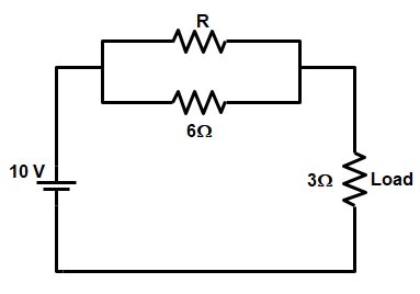
Ques 18. In the circuit given below, the value of R required for the transfer of maximum power to the load having a resistance of 3Ω will be?
3Ω
10Ω
6Ω✓
9Ω
For Maximum Power to be transferred the Load Resistance RL and the internal Resistance Rth should be Equal
Note:- If there is “Zero” in the option then you should check as the right Option.
For maximum power transfer to RL, R should be zero so that maximum current flows through the load resistance. and hence maximum power is transferred to the load resistance.
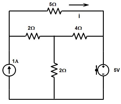
Ques 19. In the following given circuit what will be the value of current I in the 5Ω resistor?
5A
4A
2A
0A✓
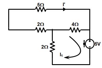
By applying the Superposition theorem In the given Network we can calculate the current in the 5Ω Resistance
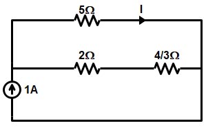
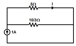
Now shorting the 5V source
The resistance 2Ω is parallel with the resistance 5Ω therefore (2Ω || 5Ω)


Please upload questions and solutions of DMRC JE 2017 paper of electrical
Q 66..Which option is correct?