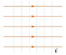
Ques 61. In a uniform electric field, field lines and equipotentials
Are parallel to one another
Intersect at 45°
Intersect at 30°
Are orthogonal✓
The equipotential surfaces associated with a uniform electric field consist of a family of planes perpendicular to the field lines.
In the case of the uniform electric field, the field lines are straight and equally spaced. Therefore, equipotential surfaces will be parallel planes at right angles to field lines.
Ques 62. During forward blocking state, the SCR has
Low current, medium voltage
Low current, large voltage✓
Medium current, large voltage
Large current, low voltage
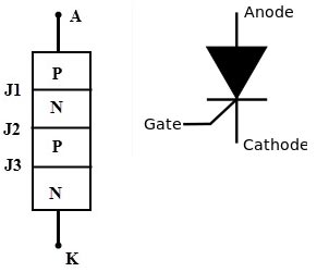
A silicon-controlled rectifier or semiconductor-controlled rectifier is a four-layer solid-state current-controlling unidirectional device (i.e. can conduct current only in one direction).
The silicon control rectifier (SCR) consists of four layers of semiconductors, which form NPNP or PNPN structures, having three P-N junctions labeled J1, J2 and J3, and three terminals.
The SCR has Two state
High current Low Impedance ON state
Low current High Impedance OFF state
Forward Blocking Mode
The SCR is said to be forward-biased when the anode is made positive with respect to the cathode. Due to this forward bias, the junctions J1 and J3 are forward biased and J2 is reverse biased. Hence the forward voltage is to be held by junction J2.
A very small current flows from anode to cathode. This current is called forward leakage current. This current is of the order of few milliamperes. In the forward blocking mode, the voltage can be increased by VBO. When the forward voltage reaches VBO, the SCR turns on. During forward Blocking Mode SCR acts as a Resistor.
Ques 63. Turn-on time for an SCR can be reduced by using a
Rectangular pulse of high amplitude and narrow width✓
Rectangular pulse of low amplitude and wide width
Triangular pulse
Trapezoidal pulse
SCR turn on Time is reducing by applying Rectangular Pulse of high amplitude and Narrow width
Ques 64. The disruptive critical voltage will
Decrease with the increase of moisture content in the air✓
Increase with the increase of moisture content in the air
Increase with the decrease of moisture content in the air
Decrease with the decrease of moisture content in the air
The critical disruptive voltage is defined as the minimum phase to the neutral voltage at which corona occurs.
The disruptive critical voltage depends on the following factors:
The atmospheric condition
The condition of the surface of the conductor
The conductor configuration
Dust and dirt. Due to the presence of dust and dirt, less voltage gradient is required for sustained discharge. The critical disruptive voltage is reduced due to dust and dirt and therefore the corona loss is more.
Rain, snow, hail, and fog. Bad weather conditions such as rain, storm, hail, etc. reduce the critical disruptive voltage, and thus there is more corona loss. Corona loss is less in a fail weather condition.
The diameter of the conductor: With the increase in the diameter of the conductor the critical disruptive voltage is increased.
Ques 65. What type of insulator will be used in the direction of the transmission line is to be changed?
Pin-type
Suspension type
Strain type✓
Shackle type
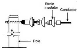
Strain type insulators are used for handling the mechanical stress at the angle position of the line i.e Dead end, intermediate anchor tower, corner, sharp curve.
These insulators reduce the excessive tension on the line under such abnormal conditions. For low voltage lines below 11 kV shackle insulators are used but for higher voltages strain insulators are used. Assembly of the suspension insulators is used as a strain insulator. The discs of the strain insulators are in a vertical plane instead of the horizontal plane as in the suspension insulators In the case of conditions like the crossing of the river, there is excessive tension on the line. In such a case, two or more string of the insulators are used in Parallel.
Ques 66. Which statement about SF6 gas is correct?
SF6 gas is toxic✓
SF6 gas is lighter than air
SF6 gas is yellow in color
SF6 gas has the pungent smell
Pure SF6 gas is colorless, odorless, tasteless, and non-toxic, it is chemically stable and non-flammable.
SF6 gas, when used in electrical equipment, gets decomposed when electrical discharges occur. During the Arc extinction process, SF6 is decomposed into atoms, electrons, and ions.
These atomic components do not recombine completely to form the original SF6 gas on cooling. They form low molecular gaseous sulfur fluorides and compounds with the contact metals principally SF4 and SF2, together with a small amount of S2, F2, S, and F. Some of the decomposition products are toxic and harmful to personnel working with the equipment.
Ques 67. One coulomb of electrical charge is contributed by how many electrons?
6.24 × 10¹⁸✓
1.6 × 10¹⁹
1019
None of these
The charge possed by the proton is equal to 1.602 × 10⁻¹⁹ whereas the charge possed by the electron is equal to -1.602 × 10⁻¹⁹.
The symbol Q often denotes charge and the SI unit of electric charge is the coulomb (C).
The charge on one electron is 1.602 × 10⁻¹⁹, so the one-coulomb charge is defined as the charge possessed by the total number of ( 1/ 1.602 × 10⁻¹⁹) electrons i.e. 6.24 x 10¹⁸ number of electrons.
Ques 68. A dynamic system with input x(t) and output y(t) is represented by the following:
y(t)= ax(t) +bx2(t)
y(t)= ax sin(t)
y(t)= f(x(t),t)✓
None of these
If the impulse response of the discrete-time LTI system is not identically zero then the system is called a Dynamic system or system with memory.
The Dynamic system is represented by y(t) = f(x(t),t)
For example, the systems defined below are dynamic or memory systems. y(t)=x(t-1) y(t)=x(t)+x(t+2)
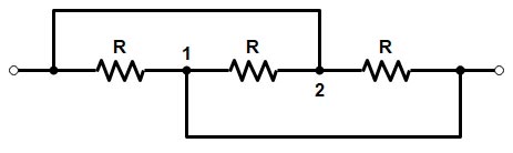
Ques 69. Three equal resistors each equal to R ohm are connected as shown in fig. The equivalent resistance between points A and B is:
R
3R
2R/3
R/3✓
In the given Figure All the Three resistors are in parallel to each other therefore their equivalent resistance is 1/Req= 1/R + 1/R + 1/R = 3/R
Req= R/3
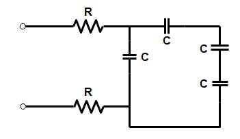
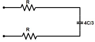
Ques 70. The time constant of the circuit shown in fig. is:
RC/3
4RC/3
2RC/3
8RC/3✓
Since 3 capacitors are in series, therefore, its equivalent resistance
Ques 71. If the current in the armature of the d.c series motor is reduced to 5%, the torque of the motor will become:
50% of the Previous Value
25% of the Previous Value✓
150% of the Previous Value
100% of the Previous Value
In DC series Motor, the torque is directly proportional to the square of the armature current
T ∝ Ia2
So if the armature current is reduced to 5% then torque is
T = 52
T = 25%
Ques 72. If the excitation of an alternator operating in parallel with other alternators decreases, its:
Power factor becomes more leading✓
Output KW will change
Power factor becomes more lagging
Power factor becomes unity
When the excitation of the alternator is decreased below normal excitation then reactive power will change and the active power output (W or KW) of the alternator will remain unchanged.
The under-excited alternator delivers a leading current to the infinite bus bar.
It is because the leading current produces an adding m.m.f to increase the under excitation.
Similarly, an overexcited alternator operates at a lagging power factor and supplies lagging reactive power to an infinite bus bar.
Conclusion:
From both of the above conditions i.e whether the excitation is increased or decreased its power factor change.
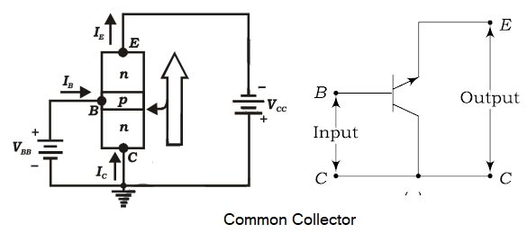
Ques 73. The output signal of a common-collector amplifier is always:
Larger than the input signal
In phase with the input signal✓
Out of phase with the input signal
Exactly equal to the input signal
In a common-collector configuration, the collector terminal of a transistor is connected as a common terminal between input and output as shown in fig. The base and collector terminals are used to apply the input signal whereas the output signal is obtained. The CC configuration is also commonly known as the emitter follower or the voltage follower.
This is because the output signal across the emitter is almost the replica of the input signal with little loss. In other words, the output voltage follows the input voltage and hence the voltage gain will be a maximum of one.
Ques 74. A current is said to be alternating when it changes in:
Magnitude
Direction
Both magnitude and direction✓
None of these
An alternating current (AC) is an electric current of which magnitude and direction vary, unlike direct current, whose direction remains constant.
Ques 75. Hysteresis loss in a transformer depends upon:
Frequency✓
Supply voltage
Square of the frequency alone
Square of the voltage alone
Hysteresis losses are also known as Iron Loss or Core Loss and it is always constant.
Hysteresis loss is due to the reversal of magnetization of the transformer core whenever it is subjected to the alternating nature of magnetizing force.
Hysteresis Loss is given by
Hysteresis Loss = Kh × BM1.67 × f × v watts
where Kh = Hysteresis constant depends upon the material Bm = Maximum flux density f = frequency v = Volume of the core
Hence the Hysteresis losses are directly proportional to the supply frequency.
For SSC JE Conventional Solved Paper 2017 CLICK HERE
For SSC JE Conventional Solved Paper 2016 CLICK HERE


Please upload questions and solutions of DMRC JE 2017 paper of electrical
Q 66..Which option is correct?