
Ques 44. The time constant of RL circuit is.
- L/R✓
- R/L
- R2/L
- L2/R
An LR Series Circuit consists basically of an inductor of inductance L connected in series with a resistor of resistance R. Time Constant The time constant of an RL circuit is defined as the time taken by the inductor current to reach steady-state if the initial rate of rising is maintained. or The time constant of the RL circuit is defined as the amount of time necessary for the current in the circuit to reach 63.2% of its maximum value. or The time constant of a series RL circuit is equal to the ratio of the value of inductor to the value of resistance τ = L/R Where T = time constant in seconds,
L = inductor in Henry,
R = resistance in ohms.
Ques 45. The permittivity of air is
- 4π x 10-7 F/m
- 8.854 × 10⁻¹² F/m✓
- 9 × 10⁹ F/m
- 8.854 × 10⁻¹¹ F/m
In electromagnetism, absolute permittivity, often simply called permittivity, usually denoted by the Greek letter ε (epsilon), is the measure of resistance that is encountered when forming an electric field in a particular medium. The lowest possible permittivity is that of a vacuum. Vacuum permittivity, sometimes called the electric constant, is represented by ε0 and has a value of approximately 8.85 × 10⁻¹² F/m. The SI unit for permittivity is farad per meter (F/m). Note:- In electromagnetism, permeability is the measure of the ability of a material to support the formation of a magnetic field within itself. The magnetic constant has the exact (defined) value (µ0 = 4π × 10−7H·m−1
Ques 46. The form factor of a sinusoidal voltage is
- 1.414
- 0.632
- 0.707
- 1.11✓
In electrical, the form factor of an alternating current waveform (signal) is the ratio of the RMS (root mean square) value to the average value (mathematical mean of absolute values of all points on the waveform). Form factor is the ratio of R.M.S value/Average value R.M.S value of sine wave = 0.707 Average value of sine wave = 0.637 Therefore Form factor = 0.707/0.637 =1.109 ≅ 1.11
Ques 47. Inside a conducting sphere _______ remain constant.
- Charge
- Potential✓
- Current
- Electric Flux Density
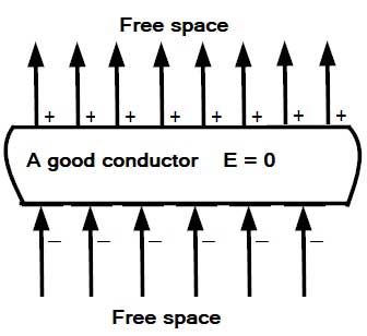
When the magnitude of the induced field becomes equal to that of the applied field, the net field intensity inside the conductor will become zero That is the Electric field due to the charges inside the conductor is directed opposite to the electric field outside which the field inside the conductor originated. Remember: The charges move in a conductor so as to kill the external field Consequently, no further movement of charges will take place. That is, the static condition will be reached after a brief transient period during which charges move to the surfaces. External field lines terminate on the bottom surface and emerge from the top surface, as shown in the figure. Since field intensity inside a good conductor is zero, the potential gradient, which is numerically equal to the field intensity, is also zero. Accordingly, the potential has the same value everywhere inside a good conductor. The relation between electric field and potential is given as E = -dv/dr Where dv/dr is the rate of change of potential with distance also known as a potential gradient. Since field intensity inside a good conductor is zero therefore dv = 0.dr On integrating.V=- ∫dr.0 Integration of 0 is a constant Therefore, V = constant The potential inside a hollow conducting shell is constant. The constant value can be zero or non-zero. Note:– E is a vector & V is a scalar quantity. But if V is zero, then surely E has to be zero; the reverse case is not true always.
-dv/dr = 0
Ques 49. Calculate the value of each of the two resistors of value 100Ω connected in parallel across the 100V supply.
- 100 W✓
- 2000 W
- 1500 W
- 1.5 W
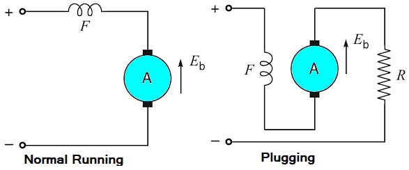
Ques 50. Plugging method of braking is applied to induction motor by;
- Reduce the applied voltage
- Reversing the rotor current externally
- Interchanging two phases of the stator✓
- Opening the rotor and connecting across the resistor
The disadvantages of this method are: 1. The kinetic energy of the motor is dissipated in the external resistance in the form of heat. So, this method of braking is inefficient. 2. The braking in this method fails in case of failure of the supply.
Ques 51. The motor used in electric traction is
- Synchronous Motor
- 3 phase induction motor✓
- DC shunt Motor
- Single-phase induction motor
For electric traction, DC series motors are best suited. DC series motors and AC series motors are very much recommended, as they provide a high starting torque Nowadays three-phase induction motors are also being used.
Ques 52. The power factor of the load when one of the wattmeters indicates the negative reading during the 3-phase power measurement using the two wattmeter method is
- Above 0.5
- Below 0.5✓
- Unity
- Above 0.707
The reading of two wattmeter can be expressed as W1 = VLILcos(30 + φ) (i) When PF is unity ( φ = 0°) W1 = VLILcos30° Both wattmeters read equal and positive reading i.e upscale reading (ii) When PF is 0.5 (φ = 60°) W1 = VLILcos90° = 0 Hence total power is measured by wattmeter W2 alone (iii) When PF is less than 0.5 but greater than 0 i.e ( 90° > φ > 60°) W1 = Negative The wattmeter W2 reads positive (i.e.upscale) because for the given conditions (i.e. ( 90° > φ > 60°), the phase angle between voltage and current will be less than 90°. However, in wattmeter W1, the phase angle between voltage and current shall be more than 90° and hence the wattmeter gives a negative (i.e. downscale) reading. Wattmeter cannot show negative reading as it has only a positive scale. An indication of negative reading is that pointer tries to deflect in a negative direction i.e. to the left of zero. In such a case, reading can be converted to positive by interchanging either pressure coil connections or by interchanging current coil connections. Remember that interchanging connections of both the coils will have no effect on wattmeter reading. (iv) When P.F reads zero (φ = 90°) Such a case occurs when the load consists of pure inductance or pure capacitance W1 = VLILcos(30 + 90°) = – VLILsin30° In this condition, the two wattmeter reads equal and opposite i.e W1 + W2 = 0
W2 = VLILcos(30 − φ)
W2 = VLILcos30°
W2 = VLILcos30°
W2 = positive (since cos(−φ) = cosφ)
W2 = VLILcos(30 − 90°) = VLILsin30°
Ques 52. In moving, Iron type meter has the non-linear scale as:
- θ ∝ Irms
- θ ∝ I2rms✓
- θ ∝ Vrms
- θ ∝ R2
A moving coil instrument must take the current to give a non-zero reading. A moving iron type of current meter is based on the principle of repulsion between similar magnetic poles. If two soft iron bars AB and CD are placed inside a current-carrying coil wound on a non-magnetic former, the two soft iron bars will get magnetized in the same direction with the two ends facing each other having the same polarity as shown in Fig. The two similar poles will repel each other. If the direction of the current through the coil is reversed the polarities of the two iron bars will be reversed but similar poles will again be facing each other and these will again repel. If one of the two soft iron pieces is fixed and the other is free to move, this motion can be used to measure current by attaching to the movable iron bar a pointer that will move over a calibrated scale. A linear scale is one in which divisions or markings are equidistant and the pointer moves over equal distances for equal chances of current. A linear scale is used by the moving coil type meter because the deflection of the pointer is directly proportional to the current through the coil. A non-linear scale is one in which the divisions are not equidistant and the pointer does not move over equal distances for equal changes of current. In the case of moving iron type of current meters, the force of repulsion or attraction is proportional to the square of the current passing through the coil. When the current through the coil is doubled, the strength of the magnetic. If the supply frequency is 50 Hz, the torque varies between zero and a maximum of 100 times a second, so that the moving system (due to its inertia) takes up a position corresponding to the mean torque, where the mean torque ∝ mean value of the square of the current = kl2 where k = a constant for a given instrument I = r.m.s. value of the current. Thus the moving-iron instrument can be used to measure both direct current and alternating current, and in the latter case, the instrument gives the r.m.s. value of the current. Owing to the deflecting torque being proportional to the square of the current, the scale divisions are not uniform, being cramped at the beginning and open at the upper end of the scale.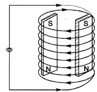
Ques 53. The number of electrons constituting 1 C of charge
- 0.625 × 10¹⁹✓
- 4 × 10⁷
- 8.854 × 10⁹
- 1.6 × 10¹⁹
We know that the charge of an electron is 1.6 × 10¹⁹ Coulomb Now if the charge is 1.6 × 10⁻¹⁹ C, then the number of electrons is 1 Now if the charge is 1 C then the number of electrons is 1C = 1/1.6 × 1019 = 625 × 1019


please explain Q64..
Dear sir kindly don’t highlight the answer inthe options itself..so it drastically reduces the thinking capacity of aspirants ..please in explanations give the answer
Hello, Natesh I am working on it. Need some time to Makes those changes
Question no 2…is answer right???