Ques 54. A three-phase induction motor is analogous to
Generator
Rotating transformer✓
Rotating Motor
Rotating converter
Analysis of transformer model is very easy to visualize then induction motor so, the induction motor is generalized as transformer because of following reasons :
Operations of both induction motor and transformer are somewhat the same that is “both operate on the same principle of induction”.
Both have two windings
Transformer: primary and secondary
Induction motor: Stator and rotor
Rotor windings are short-circuited at the end to produce torque for the rotation.
Voltage ratios of two windings in both the cases are of a similar kind
Transformer: 1:n where ‘n’ is voltage transfer ratio
Induction motor: 1:s where ‘s’ is slip(also voltage ratio)
Both have the core in between two windings :
Transformer: Ferromagnetic material
Induction Motor: Air gap
In fact, the AC induction motor was patented as Rotating Transformer by Nikola Tesla. The reason behind that is the stator (stationary part) is essentially the primary side of the transformer and the rotor Rotating part is the secondary side of the transformer.
Because of the above reasons Induction motor is called a two windings transformer with secondary short-circuited.
Ques 55. In power system, active power control is related to
Frequency control✓
Both voltage and frequency control
Voltage control
Steam control
The flows of active power and reactive power in a transmission network are fairly independent of each other and are influenced by different control actions. Hence, they may be studied separately for a large class of problems.
Active power control is closely related to frequency control, and reactive power control is closely related to voltage control.
The frequency of a power system is proportional to the rotating speed of the synchronous generators operating in the system.
The generators in the same ac system are synchronized, running at the same speed. Increasing the electrical load in the system tends to slow down the generators and reduce the frequency.
The task of frequency control of the system is to increase or reduce the generated power so as to keep the generators operating in the specified frequency range.
Ques 56. The full-load efficiency at a unity power factor of a 230/115V, 2 KVA single phase transformer having a CU loss of 60 W at half load and iron loss of 50 Watt is
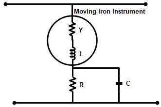
Ques 57. The purpose of the capacitor in the figure is
To increase the impedance
To compensate the frequency error✓
To bypass the resistor R
To compensate for the error for the supply Variation.
Errors in Ml instruments
The sources of error in moving-iron instruments can be divided into two categories, i.e. thou which occur with d.c. and a.c. both and those which occur with d.c. only.
With both d.c. and a.c.
(i) Hysteresis error: The hysteresis error is a serious error in the moving-iron instruments and occurs with both d.c. and a.c. supply. Due to hysteresis in the iron, the instrument readings al higher for descending values of current or voltage than the corresponding ascending values. The error is reduced by making the iron paths very small in the proportion of the total magnetic circuit.
(ii) Error due to stray magnetic fields: The presence of a stray magnetic field mainly affects the deflecting torque and the disturbance is greatest when the operating field and the interfering stray magnetic fields are parallel. With d.c. supply, a weak alternating field is non-interfering.
But with a.c the effect is usually negligible if the frequency of the stray magnetic fields is different than that of an operating field. This error can be almost eliminated by enclosing the movement within a shield of high-permeability magnetic alloy and calibrating the instrument with the shield in position.
With AC only
(i) Error due to change in frequency: As the frequency varies, the inductive reactance of the working coil varies so that the total impedance of the coil varies due to change in frequency However this is of importance in the case of voltmeters owing to its high impedance. If L is the inductance of the coil, R. its resistance, r is its series resistance and E is the applied voltage, then the working current is, E
So now if frequency varies, the working current for a given applied voltage changes thus producing an error in deflection. This can be compensated by making inductance L much smaller as compared with (R + r) the time constant for such voltmeters is usually in the range of .0003 tc .0007.
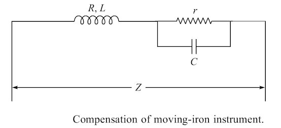
One method of compensation is to connect a capacitor of suitable capacitance in parallel with the series resistance r as shown in Figure 4.4. such that the impedance of the whole circuit it independent of frequency.
So now if frequency varies, the working current for a given applied voltage changes thus producing an error in deflection. This can be compensated by making inductance L much smaller as compared with (R + r) the time constant for such voltmeters is usually in the range of .0003 to .0007.
One method of compensation is to connect a capacitor of suitable capacitance in parallel with the series resistance r as shown in Figure. such that the impedance of the whole circuit of the instrument becomes independent of frequency if C = L/r2, where C is the capacitance of the condenser.
Ques 58. The unit of magnetomotive force is
AT/Wb
Wb/S
Wb
AT✓
Magnetomotive force is any physical cause that produces magnetic flux. It is analogous to electromotive force or voltage in electricity.
The standard definition of magnetomotive force involves current passing through an electrical conductor, which accounts for the magnetic fields of electromagnets. Permanent magnets also exhibit magnetomotive force, but for different reasons.
The unit of magnetomotive force is the Ampere-Turn (AT), represented by a steady, direct electric current of one ampere flowing in a single-turn loop of electrically conducting material in a vacuum.
The Gilbert (Gi), is the CGS unit of magnetomotive force. The unit is named after William Gilbert, an English physician, and natural philosopher.
Note:- (“R”) is the reluctance in ampere-turns per Weber (a unit that is equivalent to turns per Henry).
Weber is the SI unit of Magnetic Flux
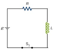
Ques 59. A coil of resistance 10Ω and inductance 2H is connected to a 100 V DC supply through a switch. The initial rate of change of current at the instant of closing the switch.
5V/sec
100 V/sec
10 V/sec
50 V/sec✓
The circuit diagram for a series connected L-R circuit is shown in Fig. When switch S closed, then by Kirchhoff’s voltage law:
V = VL + VR ————-(1)
The battery voltage V is constant. The Voltage across the inductance is the induced voltage, i.e
VL = L x change of current/change of time
VL = Ldi/dt
The voltage drop across R. VR is given by iR Hence, at all times:
VL = Ldi/dt + iR
At the instant of closing the switch, the rate change of current is such that it induces an e.mf in the inductance which is equal and opposite to V.
Hence V = VL + 0 i.e V = VL
From equation 1 because V = VL then VR = 0, i = 0
And now at the instant of closing the switch i = 0. Hence from the equation 1
V = L x Initial rate of change of current
Initial rate of change of current = V/L
Now coming back to the question
Initial rate of change of current = 100/2 = 50 V/sec
Ques 60. When reverse biased, a PN junction diode acts as a
An Open circuit✓
A rectifier
A short circuit
An amplifier
A diode is a two-electrode (two-terminal) device that acts as a one-way conductor. The most basic type of diode is the PN-Junction diode. When forward bias PN junction diode conducts. When reverse biased, it effectively blocks the flow of charge (current).
A diode permits current Bow when the voltage on the anode is positive with respect to the voltage on the cathode.
A diode inhibits current flow when the voltage on the anode is negative with respect to the voltage on the cathode.
A diode is called forward biased when the anode is positive with respect to the cathode. A forward-biased diode functions like a closed switch permitting current flow.
A diode is called reversed biased when the anode is negative with respect to the cathode. A reversed biased diode functions like an open switch (infinite Resistance) inhibiting current flow.
Based on the characteristics of a switch the following statements can be considered about the ideal diode:
When forward-biased enclosed switch):
The diode has no resistance.
The diode does not limit the circuit current
The diode has no voltage drop across its terminals.
When reverse biased (open switch):
The diode has infinite resistance.
The diode does not pass current.
The diode drops the applied voltage across its terminals.
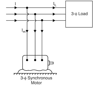
Ques 61. The machine used for power factor correction is
Universal Motor
Synchronous Motor✓
Stepper Motor
Induction Generator
A synchronous condenser is a synchronous motor running without the mechanical load. The Synchronous motor takes a leading current when over-excited and therefore behaves as a capacitor. When such a machine is connected in parallel with the supply, it takes a leading current which partly neutralizes the lagging reactive component of the load. Thus the power factor is improved.
Advantages
A synchronous condenser has an inherently sinusoidal waveform and the voltage does not exist.
It can supply as well as absorb kVAr.
The PF can be varied in smoothly.
It allows the overloading for short periods.
The high inertia of the synchronous condenser reduces the effect of sudden changes in the system load and improves the stability of the system.
It reduces the switching surges due to sudden connection or disconnection of lines in the system.
The motor windings have high thermal stability to short-circuit currents.
By varying the field excitation, the magnitude of current drawn by the motor can be changed by any amount. This helps in achieving step-less control of the power factor.
The faults can be removed easily.
Disadvantages
There are considerable losses in the motor.
The maintenance cost is high.
It is not possible to add or take away the units and alter the rating of the synchronous condenser.
For small rating it is uneconomical.
As a synchronous motor has no self-starting torque, therefore, auxiliary equipment has to be provided for this purpose
Ques 62. The value of resistance in a Potential divider arrangement to convert a basic d’Arsonval meter movement with an internal resistance of 100Ω and a full-scale current of 1mA to a multirange DC voltmeter with ranges 0-150V and 0-300V are.
135.5 KΩ, 134 KΩ
149. 9 KΩ, 150 KΩ✓
144.9 KΩ, 140 KΩ
149.5 KΩ, 155.5 KΩ
The full-scale voltage of Moving coil based measuring instrument such as multirange ammeter is
VM = IFSD (RMC + RS ) VM = VMC + IFSD RS ——–1
where VM is the full‐scale voltage of the selected range.
IFSD = Full scale deflection current
Rs = series Resistance
RMC = Resistance of Moving the coil
VMC = Voltage of the moving coil
VMC = 1mA x 100Ω or 1 x 10-3 x 100 = 0.1V
Now from eqn 1
Rs = (VM – 0.5)/1
Note:- There are two methods two solve this problem
Conventional Method
Alternative Modified Method
In conventional connection, resistors are selected one by one to satisfy
Since the two ranges are given in the question, therefore, the two resistor RS1 and RS2 are connected in series with RMC. The d’Arsonval meter uses a modified method.
Range 1
In the first range (0-150 V) only RS1 is used and the maximum voltage drop on RS1 is
Rs1 = (150 – 0.5)/1 = 149.9 KΩ
Range 2
In the 2nd range (0 – 50 V) RS1 +RS2 is used and the maximum voltage drop on RS2 is
(300 – 150) = 150 V
Thus RS2 = 150/1 = 150 KΩ
Ques 63. Curie point is
The temperature at which a magnetic material gains its magnetic property
The temperature at which a magnetic material loses its magnetic property✓
The voltage at which a magnetic material loses its magnetic property
The voltage at which a magnetic material gain its magnetic property
In physics and materials science, the Curie temperature (TC), or Curie point, is the temperature at which certain materials lose their permanent magnetic properties, to be replaced by induced magnetism. The Curie temperature is named after Pierre Curie, who showed that magnetism was lost at a critical temperature
Ques 64. A magnetic material of 300 mWb in a coil of hundred turns is reverted in 0.2 seconds. The average induced EMF is
600 V
300 V
-300 V✓
1200 V
Since the flux reverses the flux changes from +200 mWb to -200 mWb hence the total change of flux is 400mWb
Induced EMF = -Ndφ/dt = -100(400 x 10-3)/0.2 = -300V
Dear sir kindly don’t highlight the answer inthe options itself..so it drastically reduces the thinking capacity of aspirants ..please in explanations give the answer
admin
Hello, Natesh I am working on it. Need some time to Makes those changes


please explain Q64..
Dear sir kindly don’t highlight the answer inthe options itself..so it drastically reduces the thinking capacity of aspirants ..please in explanations give the answer
Hello, Natesh I am working on it. Need some time to Makes those changes
Question no 2…is answer right???