
Ques 11. Which of the following is not the method of earth resistance measurement?
- Potier Method✓
- Three-point Method
- Two-point Method
- Fall of Potential Method
To maintain sufficiently low resistance values of grounding systems, periodic testing is required. The testing involves measurement to ensure that they do not exceed design limits. The methods of measuring and testing the ground resistance and soil resistivity are as follows: This method may be used to measure the resistance of a single driven ground rod. It uses an auxiliary ground rod whose resistance is either known or can be measured. The resistance value of the auxiliary ground rod also must be very small compared to the resistance of the driven ground rod so that the measured value can be assumed to be wholly contributed by the drivel ground rod. For example, this test might be applicable in the measurement o resistance of the single driven ground rod for a residence or in congested areas where finding room to drive two auxiliary rods may be a problem. In this case, the municipal metallic water supply line can be assumed as the auxiliary ground rod whose resistance value is approximately 1Ω or less. This value is quite small compared to the value of a single driven ground rod, whose value is in the order of 25Ω. The reading obtained is that of the two grounds in the series. The lead resistances will also be measured and should be deducted from the final measurements. This method is usually adequate where a go, no-go type of test is required. This method is similar to the two-point method except it uses two auxiliary rods. To obtain accurate values of resistance measurements, the resistance of the auxiliary electrodes should be approximately equal to or less than that of the electrode under test. The connections for the three-point method are shown in Figure Either AC of 50Hz or DC may be used for making this test. The advantage of using AC is that it minimizes the effects of stray currents on measurement readings. However, if stray currents happen to be of the same frequency, the error will be introduced in the readings. The use of DC for making this test will totally eliminate the AC stray currents. The use of direct current for making this test will totally eliminate the ac stray currents. However, stray direct current and formation of gas around the electrode will introduce errors in the readings when using direct current for this test. The This method measures grounding electrode resistance based upon the principle of the potential drop across the resistance. It also uses two auxiliary electrodes (one current rod and the other potential rod) that are placed at a sufficient distance from the test electrodes. A current of known magnitude is passed through the electrode under the test and one of the auxiliary electrodes (current rod). The drop in potential between the electrode under the test and the second auxiliary electrode (potential rod) is measured. Ground Resistance Measurements
Two-Point Method

Three-Point Method

average of two readings will give an accurate test value.Fall of Potential Method

The ratio of the voltage drop (V) to the known current (I) will indicate the resistance of the grounding circuit. Either a dc or A.C voltage source may be used for conducting this test.
Ques 12. For the given circuit, the maximum power in the load can be

- 893 mW✓
- 658 mW
- 840 mW
- 10 mW
For Maximum Power to be transferred the Load Resistance RL and the internal Resistance Rth should be Equal. Rth = RL Thevenin’s resistance can be found by replacing 10 V source with a short-circuit. As seen from Fig. , Rth = 2 + 2 + (6 || 6) = 7Ω. We will remove the load resistance RL and find the equivalent Thevenin’s source for the circuit to the left of terminals A and B. As seen from Fig. Vth equals the drop across the vertical resistor of 6Ω because no current flows through 2Ω and 2Ω resistors Now from voltage division Rule Vth = 10 × 6 ⁄ (6 + 6) = 5 V Now the Load Current IL from the above circuit is IL = Vth ⁄ (R + RL) = 5 ⁄ (7 + 7) = 5 ⁄ 14 IL = 0.357 A Power = I2RL P = (0.357)2 × 7 = 0.892 Watt or 892 mW


= 0.1274 × 7
Ques 13. What is the composition of alloy “Kanthal” ( used as the heating element in an electrical heating system)?
- Chromium, aluminum, cobalt
- Chromium, copper, cobalt
- Chromium, aluminum, nickel
- Chromium, aluminum, cobalt, iron✓
Kanthal is the trademark for a family of iron-chromium-aluminum (FeCrAl) alloys used in a wide range of resistance and high-temperature applications. Kanthal FeCrAl alloys consist of mainly iron, chromium (20–30%) and aluminum, and cobalt (4–7.5 %). The first Kanthal FeCrAl alloy was developed by Hans von Kantzow in Hallstahammar, Sweden. The alloys are known for their ability to withstand high temperatures and have intermediate electric resistance. As such, it is frequently used in heating elements.
Ques 14. During discharging of the capacitor of C = 100 μF through the resistor of 1 KΩ applied with 50 V. The voltage at the time constant is
- 50 V
- 15 V
- 18.5 V✓
- 100 V
A general conceptual definition of a time constant can be given as follows: A time constant is a measure of the time it takes to observe significant changes in a given process. When the capacitor is discharging When the capacitor discharge the time constant can be defined as the time required for the charging current of the capacitor to fall to 0.368 ≅ 0.37 of its initial maximum value, starting from its maximum value. Hence At 1 time constant ( 1T ) Vc = 0.37Vc. Therefore, Vc = 0.37 x 50V = 18.5 V
Ques 15. What is the force of attraction between two electric charges of opposite polarity having 1 coulomb each when placed at a distance of 1 m?
- 8.854 × 10¹² Newton
- 5.854 × 10¹² Newton
- 9 × 10⁹ Newton✓
- 4π × 109 Newton
COULOMB’S LAW AND CONCEPT OF PERMITTIVITY Coulomb’sfirst law states that like charges repel each other while opposite charges attract each other. Coulomb’s second law states that the Force of attraction between two opposite charges or force of repulsion between two like charges is If we assume the charges to be of magnitude (Q) and (q) separated by a straight distance d, then from Coulomb’s second law we can write F ∝ Q.q ⁄ d2, (F) being the force of repulsion if both charges are alike or force of attraction if the charges have opposite polarity. The force (F) is measured in Newtons when the magnitude of the charges is expressed in Coulombs and the distance in meters. $F = K\dfrac{{Q.q}}{{{d^2}}}$ where k is Coulomb’s constant (k = 9 ×10⁹ N m2 C−2) If Q = q = 1 coulomb and d = 1 meter $\begin{array}{l}F = 9 \times {10^9}\dfrac{{1 \times 1}}{{{1^2}}}\\\\F = 9 \times {10^9}\end{array}$ If Q = q = 1 coulomb and d = 1 meter. This gives rise to the definition of unit charge (i.e. 1 Coulomb which means that it is such a charge that when placed at one meter apart from another similar charge experiences a force of 9 x 10⁹ Newton in the vacuum.
Ques 16. The force on each of the conductors infinitely long and carries a current of 1 A separated by a distance of 1m in a Vacuum is:
- 8.854 × 10¹² Newton
- 5.854 × 10¹² Newton
- 2 × 10⁷ Newton✓
- 4π × 109 Newton
Force Law For Current-Carrying Conductors The force (F) per unit length (L) between two wires carrying currents I1 and I2 separated by a distance d in a vacuum is given by: $\dfrac{F}{l} = \dfrac{{{\mu _o}{I_1}{I_2}}}{{2\pi d}}$ Where μo is Vacuum permeability or permeability of free space = 4π × 10-7 H/m Now the given data Current in the wire = I1 = I2 = 1A The distance between the wire d = 1m Putting the value in the above equation $\begin{array}{l}\dfrac{F}{l} = \dfrac{{{\mu _o}{I_1}{I_2}}}{{2\pi d}}\\\\\dfrac{F}{l} = \dfrac{{4\pi \times {{10}^{ – 7}} \times 1 \times 1}}{{2\pi \times 1}}\\\\\dfrac{F}{l} = 2\pi \times {10^{ – 7}}\end{array}$
Ques 17. The magnetic field Intensity experienced by a unit N-pole at any point in a circle of ‘r’ meters away from the center of the bunch of N conductors carrying a current of I amperes each is:
- NI ⁄ 4πr Tesla
- NI ⁄ 2πr Tesla
- NI ⁄ 4πr Oersted
- NI ⁄ 2πr Oersted✓
Magnetic field Intensity (H) is also called Magnetic field Strength, Magnetic Intensity, Magnetic field, Magnetic Force, and Magnetization Force. Magnetic Field Strength (H) gives the quantitative measure of the strongness or weakness of the magnetic field. Suppose that a current of I amperes flows through a coil of N turns wound on a toroid of length I meters. The MMF is the total current linked to the magnetic circuit i.e IN ampere-turns. If the magnetic circuit is homogeneous and of a uniform cross-sectional area, the MMF per meter length of the magnetic circuit is termed the magneticfield strength, magnetic field intensity, or magnetizing force. It is represented by the symbol H and is measured in ampere-turns per meter (At/m). $H = \dfrac{F}{L} = \dfrac{{IN}}{l}$ Hence the magnetic field Intensity can be defined as the ratio of applied MMF to the length of the path that it acts over. If N conductors are grouped together to form a coil or a cable then field strength due to current I passing through each conductor of the group can also be calculated by using the same expression. The only change will be the field strength calculated above will get multiplied by N. The value of L of the circular path is 2πr So magnetic field strength at a point ‘r’ meters away from the center of such group of “N” conductors each carrying the current I ampere is $H = \dfrac{{IN}}{{2\pi r}}$ The SI unit of Magnetic field intensity is Ampere/meter whereas in the CGS system (the centimeter–gram–second ) the unit of Magnetic field intensity is Oersted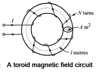

Ques 18. In a parallel operation of 1Φ transformers, a dead short circuit can happen
- Paralleling is done with incorrect polarities✓
- There is a difference in the transformation ratios of the transformer
- The power factors of the transformer don’t match that of the load
- Their percentage impedances are not equal
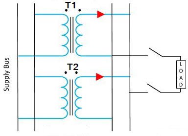
Parallel operation of Transformer The need for the operation of two or more transformers in parallel often arises due to: When two or more transformers run in parallel, they must satisfy the following conditions. Same Voltage Ratio An equal voltage ratio is necessary to avoid a no-load circulating current. Circulating current may be defined as that current that flows in transformers operating in parallel when they do not supply the load. Consider two transformers connected in parallel on their primary sides only. If the voltage readings on the secondaries are not the same, there will be circulating currents between the secondaries when they are connected in parallel. This also creates circulating currents in primaries even when the load is not connected. As the internal impedance of the transformer is small, a small voltage difference may cause a high circulating current which increases copper losses. These circulating currents produce undesirable effects as: Same percentage impedance The current shared by two transformers running in parallel should be proportional to their MVA rating. And current carried by these transformers is inversely proportional to their internal impedance. Hence the impedance of the transformer running in parallel is inversely proportional to their MVA Rating Each transformer has a particular value of impedance which may be different from the other transformer i.e their resistance to reactance is different. Consider two transformers whose ratings are in the ratio of 4: 1. It is obvious that the first transformer must have one-fourth of the impedance of the second transformer hence the current drawn by the first transformer will be 4 times to the second transformer. Due to the difference in the quality of percentage impedance, there will be a divergence of the phase angle of the two currents so that one transformer will be working with a lower and the other with a higher power factor than the combined load. Same Polarity. The polarity of all transformers running in parallel must be the same. The polarity of the transformer refers to the instantaneous direction of Induced EMF in the secondary. If the instantaneous direction of induced secondary EMF in two transformers are opposite to each other when the same input power is fed to both of the transformers, then the transformer is said to be in opposite polarity. If the instantaneous direction of induced secondary EMF in two transformers is sane when the same input power is fed to both of the transformers, then the transformer is said to be in the same polarity. The difference in the polarity causes the huge circulating current that flows in the transformer and even may lead to a dead short circuit.
Ques 19. In a salient pole synchronous machine, the MMF acting alone on the d-axis is
- NO MMF
- Field MMF
- Armature MMF
- The field and Armature MMF✓
In a synchronous machine, there are two types of rotor construction A salient pole synchronous machine is distinguished from the round rotor machine by constructional features of field poles that project with a large interpolar air gap. This type of construction is commonly employed in machines coupled to hydroelectric turbines which are inherently slow-speed ones so the synchronous machine has multiple pole pairs as different from machines coupled to high-speed steam turbines (3,000/1,500 rpm) which have a two- or four-pole structure. Salient pole machine analysis is made through the two-reaction theory. A synchronous machine with salient or projecting poles has a non-uniform air gap due to which its reactance varies with the rotor position. Consequently, a cylindrical rotor machine possesses one axis of symmetry (pole axis or direct axis) whereas a salient-pole machine possesses two axes of geometric symmetry field poles axis, called the direct axis or d-axis, and axis passing through the center of the interpolar space, called the quadrature axis or q axis, as shown in Fig The permeance offered to an MMF wave is highest when it is aligned with the field pole d-axis. Obviously, two mmf act on the d-axis of a salient-pole synchronous machine ie. field m.m.f. and armature m.m.f. The permeance offered is lowest when it is oriented at 90° to the field pole q-axis only one m.m.f., ie. armature mmf acts on the q-axis because the field has no component in the q-axis. The direct axis flux path includes two small air gaps under pole faces only whereas the quadrature axis flux path has two larger air gaps in the inter-polar regions. Hence with direct axis flux path has minimum reluctance and the quadrature axis flux path has maximum reluctance. According to the two-reaction theory, the armature mmf Fa produced by stator la is resolved into two components, one along with the direct or d-axis and another along the quadrature or q-axis. The direct axis component of Fa is Fad and the quadrature axis component is Faq. The effect of Fad is either magnetizing at demagnetizing (depending on whether the p.f. is leading or lagging), whereas the effect of Faq is entirely cross-magnetizing. Similarly, flux Φa produced by stator current la is resolved into two components Φad and Φaq Φad induces direct axis armature reaction voltage Ead and Φaq induces quadrature axis armature reaction voltage Eaq.


Ques 20. In case of an ideal transformer, the primary supply voltage and current are
- Out of phase with each other
- In phase with each other
- At Φ degree with each other, where 0 < Φ < 90°
- Mutually perpendicular to each other✓
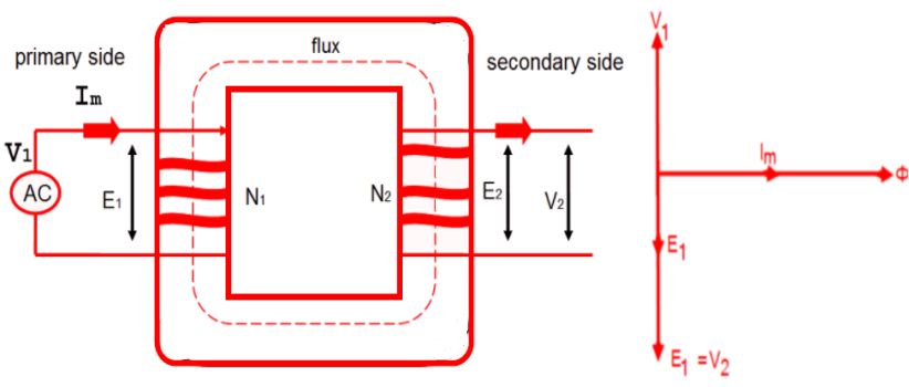
Ideal transformer Systematic Circuit Diagram


Dear sir/Madam,
I am happy to express a grate atrebute to your website , for helping students by uploading previous question paper.
In this regard my hamble request you is to send soft copy of the these previous question paper to my email address so that it will be very helpful to me for further preparation.
I am ready to pay any charges required for it ( if any)
Hope. You don’t disappoint me
Regards
Vashista
9448351139