
Ques 61. If a conductor of length 1 m moving in a magnetic field of constant flux density Bwb/m2 at an angle of θ With the direction of magnetic flux, the e.m.f induced will be (assume the conductor travels ‘x’ meters in ‘t’ seconds):
- e = Blx.sinθ
- e = Blx. cosθdx/dt
- e = Blx. sinθdx/dt✓
- e = Blxt.sinθ
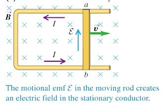
Consider a straight rod of length l moves with velocity v in a direction perpendicular to a uniform and time-independent magnetic field B, an emf is induced in the rod. The magnetic field B is uniform and directed into the page, and we move the rod to the right at a constant velocity v. A charged particle q in the rod then experiences a magnetic force F = qv × B Sin 90 with magnitude F = qvB. We’ll assume in the following discussion that q is positive; in that case, the direction of this force is upward along the rod, from b toward a. This magnetic force causes the free charges in the rod to move, creating an excess of positive charge at the upper end a and negative charge at the lower end b. This, in turn, creates an electric field E within the rod, in the direction from a toward b (opposite to the magnetic force). The charge continues to accumulate at the ends of the rod until E becomes large enough for the downward electric force (with magnitude qE) to cancel exactly the upward magnetic force (with magnitude qvB). Then qE = qvB and the charges are in equilibrium. A more interesting situation occurs when the moving conductor is part of a closed conducting path. This situation is particularly useful for illustrating how a changing magnetic flux causes an induced current in a closed circuit. Consider a circuit consisting of a conducting bar of length ℓ sliding along two fixed parallel conducting rails, as shown in Figure. A uniform and constant magnetic field B is applied perpendicular to the plane of the circuit. As the bar is pulled to the right with a velocity v, under the influence of an applied force F, free charges in the bar experience a magnetic force directed along the length of the bar. This force sets up an induced current because the charges are free to move in the closed conducting path. In this case, the rate of change of magnetic flux through the loop and the corresponding induced motional emf across the moving bar are proportional to the change in the area of the loop. Because the area enclosed by the circuit at any instant is ℓx, where x is the width of the circuit at any instant, the magnetic flux through that area is ΦB = Bℓxcosθ Using Faraday’s law, when x changes with time t at an angle θ, we find that the induced motional EMF As the magnetic flux is changing, with an angle θ, then the emf will be induced emf is given by Faraday’s law, and noting that x changes with time t at a rate dx/dt, Therefore a conductor L meter with an angleθ travels ‘x’ meters in ‘t’ seconds e = dΦ(B)/dt = BLSinθ.dx/dt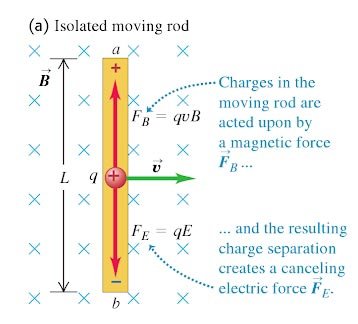
Ques.62 The cable used for high voltage application is
- Vulcanised Indian Rubber (VIR) cables
- Elastomer Insulated cable
- Polythene Insulated cable
- Gas-filled cable✓
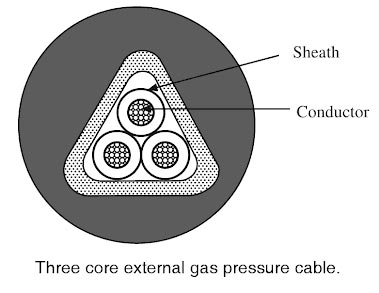
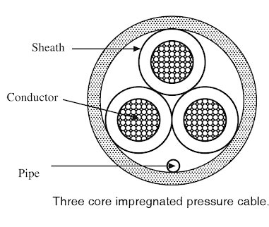
Extra high tension cable can be of 2 types Paper impregnated with petroleum jelly is normally used as the dielectric in gas-filled cables. The space between layers of paper insulation is filled with dry nitrogen gas with a pressure of 1400 kN/m2. This pressure is maintained constantly by pumps and by the lead sheath inside the cable. These cables are usually single-core cables and a small clearance is left to allow the gas to flow axially. In the case of three-core cables, clearance is not necessary because the filler spaces and strands allow the gas to flow. Gas-pressure cables are mainly of two types: External-pressure cables:- In this type of cable, the pressure is applied externally and raised to such an extent that no ionization can take place. Due to this increased pressure, radial compression takes place which tends to close voids (if any). The operating power factor of such a cable is better. The construction of the cable is similar to that of the ordinary solid type cable, except that it is triangular instead of a circular cross-section. The triangular section reduces its weight and has a low thermal resistance. This type of cable has been developed recently for application in higher voltages. The advantages of this type of cable are: (i) In comparison with the normal cable, these cables can carry from 1.4 to 1.6 times the loaf current. They can withstand double the operating voltage and transmit 2.4 to 3.2 times of the rated power. (ii) The maximum potential gradient is l 00 kV/cm and the power factor is much better. (iii) The steel pipe provides mechanical protection to the cables and acts as an ideal method of cable laying. (iv) The nitrogen in the steel pipes helps in quenching any flame. (v) Reservoirs are not needed. (vi) Maintenance cost is low. The only disadvantage of these cables is their high initial cost. 2. Internal-pressure cables. These cables are of three types: High-pressure gas-filled cables. For this type of cable, the space for the gas is provided in the dielectric itself, which is filled up by inert gases like nitrogen at a pressure of about 6 atmospheres for extra high-tension voltage cables and 12 atmospheres for super-voltage cables. This facilitates the axial flow of gas, which also passes along the un-impregnated strand. This clearance is not essential in the case of multi-core cables because the filler spaces and strands provide a low resistance path for the flow of gas. Gas-cushion cables. Here a screened space is provided in between the lead sheath and the dielectric along the length of the cable. The screened space is subdivided by means of barriers and the inert gas is stored at various points throughout the length of the cable. The advantage of this cable is that no separate arrangement is required for the transmission of pressure to the cables from outside. Hence, the cable is a complete unit with its own armoring, without requiring external pipe protection. Impregnated pressure cable:- It consists of mass-impregnated paper dielectric, which is maintained under a pressure of 14 atmospheres by means of nitrogen. Otherwise, the construction is the same as that of a solid cable. A special reinforcement is provided here to cater to the large hoop and longitudinal-stress set-up. The advantages of internal-pressure cables are: (a) No external accessories are required. (b) The cable can be used for the vertical run without any fear of leakage with suitable designs. (c) With an increase in pressure, there is an improvement in the power factor of the cable dielectric. (d) The extra super-voltage power cables are used for operating voltage beyond 132 kV. ⇒ Vulcanized India Rubber (VIR) This is the most old insulating material developed from 1880-to 1930. The advantages of VIR are, Disadvantages of VIR The use of VIR is very limited nowadays and is used for low and moderate voltage cables i.e. distribution systems only. ⇒ ELASTOMER CABLES The Elastomer cables are popularly known as Rubber cables and are probably the first type of insulation in the world. Originally it was with natural rubber for both insulation & Sheath, however, in the late 70s, it has been replaced by synthetic rubber for insulation & sheath. Elastomer cables are preferred for flexible application and in congested locations where the bending radii are very small. Elastomer cables are available from low voltage upto 33 kV (extra high Tension) grade. ⇒ Polythene Insulated cable The cables using cross-linked Polythene as the insulating material are called XLPE cables. The low-density polyethylene is treated specially due to which there occurs cross-linking of carbon atoms in it. This results in a new material that has the following XLPE cables are directly laid on the soil bed and are used for the voltages upto and including 33 kV.
Gas pressure cables
Ques 63. Reactance electromotive force in the stator of an alternator
- Is out of phase with the current
- Is in the phase with the current
- Lags current by 90°
- Lead current by 90°✓
Synchronous impedance(Zs) is the sum of armature reactance(Xa) and leakage reactance(XL). As leakage reactance can never be negative ( max it could become zero. Completely ideal case). So in order to make synchronous reactance capacitive, armature reactance(Xa) has to be negative; which is never possible. Hence synchronous reactance is always inductive. Hence, the synchronous impedance (Zs) in an alternator is virtually a pure reactance. Therefore the current in each phase lags the reactance voltage by 90° or reactance voltage Icad the current by 90°.
Ques 64. The principle of “single Resonanting atom” may be used in the measurement of
- Phase angle
- Frequency✓
- Torque
- Speed
Frequency measurement is very important in many applications of alternating current, especially in AC power systems designed to run efficiently at one frequency and one frequency only. Frequency can be measured with by far the highest precision of all physical quantities. In the radio frequency (rf) domain (say up to 100 GHz), frequency counters have existed for a long time.
Ques 65. In the case of a DC machine, the efficiency is maximum when
- Windage resistance = Windage Reactance
- Fractional Loss = Copper Loss
- Copper loss in the armature circuit = Constant loss✓
- Copper loss in the field circuit = Constant Loss
n a DC machine, the condition of maximum efficiency occurs when the variable losses (copper Losses Pc) is equal to the constant loss (Iron Losses I2LRa) (since iron loss occurs in the armature of DC machine because as the armature core is made of iron and it rotates in a magnetic field. Hence from the above discussion, it is clear that Copper loss in the armature circuit = Constant loss I2LRa = Pc
Ques 66. Which of the following is a commonly used circuit breaker in India, for rural outdoor applications ranging from 22 KV to 66 KV?
- Air Blast circuit breaker
- Plain Break Oil Circuit Breaker
- SF6 Circuit Breaker
- Vacuum circuit breaker✓
Vacuum CBS In such breakers, vacuum (VCB, degree of vacuum being in the range from 10-7 to 10-5 torr) is used as the arc quenching medium. Since vacuum offers the highest insulating strength, it has far superior arc quenching properties than any other medium. Construction Figure 13.14 shows the parts of a typical vacuum CB. It consists of fixed contact, moving contact, and an arc shield mounted inside a vacuum chamber. The movable member is connected to the control mechanism by stainless steel bellows. This enables the permanent sealing of the vacuum chamber so as to eliminate the possibility of a leak. A glass vessel or ceramic vessel is used as the outer insulating body. The arc shield prevents the deterioration of the internal dielectric strength by preventing metallic vapors from falling on the inside surface of the outer insulating cover. The vapor condensing shield is made of synthetic resin. Working Principle When the breaker operates, the moving contact separates from the fixed contact, and an arc is struck between the contacts by the ionization of metal vapors of contacts. However, the arc is quickly extinguished because the metallic vapors, electrons, and ions produced during the arc rapidly condense on the surfaces of the CB contacts, resulting in the quick recovery of dielectric strength. Application In India, where distances are quite large and accessibility to remote areas is difficult, the installation of such outdoor, maintenance-free CBS should prove a definite advantage. Vacuum CBs are being employed for outdoor applications ranging from 22 to 66 kV. Even with the limited rating of say 66-100 MVA, they are suitable for a majority of applications in rural areas. Note:- Oil circuit breakers are the most common and oldest type of circuit breakers. The rating range of circuit breakers lies in the range of 25MVA at 2.5kV and 5000MVA at 250kV. Airblast circuit breakers are a type of circuit breaker which uses a high-pressure air blast (at a pressure of 20bar) as an arc quenching medium. The range of the air blast circuit breakers is between 132kV to 400kV, with the braking capacity up to 7500 MVA. But can also be designed to cover the wide range of 66kV to 132kV. SF6 circuit breakers are designed for voltages 115kV to 230kV, the power rating of 10MVA to 20MVA, and interrupting times less than 3 cycles.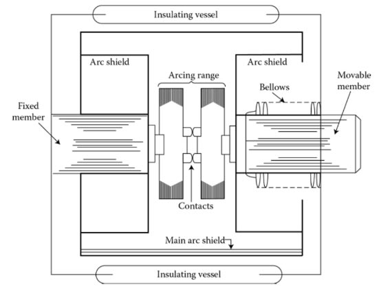
Ques 67. During the starting of a slip ring induction motor using a rotor resistance starter, the insertion of resistance in the rotor circuit causes:
- Stator current to Increase and torque to decrease
- Stator current to decrease and torque to increase✓
- Stators current to Increase and power factor to decrease
- Power factor to decrease and torque to Increase
This type of starter is used with a slip-ring wound rotor motor. These motors and starters are primarily used where the motor will start against the full load, as an external resistance is connected to the rotor windings through slip rings and brushes, which serves to increase the starting torque. Since the starting torque per phase of the induction motor is directly proportional to the rotor winding resistance and terminal voltage. Therefore, the addition of resistance in the rotor circuit not only reduces the current drawn by the motor but also increases the starting torque. By adding a suitable external resistance in the rotor circuit, such that r2‘ = x2‘, the starting torque can be made equal to the maximum torque developed. This is an ideal method used for starting slip-ring induction motors on load. This facility by which the starting torque can be varied in a slip-ring induction motor is the main advantage of this type of motor over the squirrel-cage type motors. The figure shows the wiring diagram of the rotor resistance starter. The motor is started by closing the triple pole supply switch. Then, when arm A is rotated in the clockwise direction, the motor starts. When the motor is first switched on, the external rotor resistance is at a maximum. As the motor speed increases, the resistance is reduced until at full speed, When it has reached the full rated speed, then the arm is moved to the ON position such that the external resistance gets completely cut off. Now the external resistance is completely eliminated and the machine runs as a squirrel-cage induction motor. This method is generally used for the starting of large motors.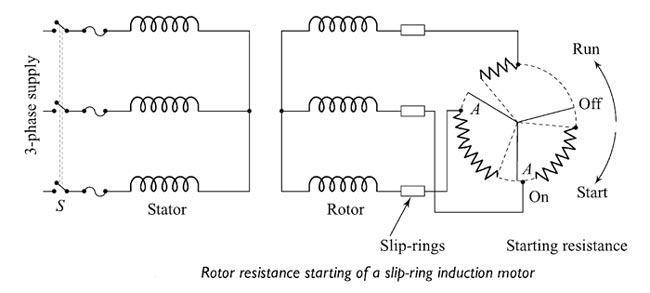
Ques 69. In the torque-slip characteristic of an induction motor, at the normal speed close to synchronism
- Directly proportional to the slip✓
- Maximum
- Inversely proportional to the slip
- Not dependent on the slip
The torque of the rotor under the running condition is $T = \dfrac{{Ks{E_2}^2{R_2}}}{{{R_2}^2 + {{\left( {s{X_2}} \right)}^2}}}$ X2 = Rotor reactance per phase At normal speed, close to synchronism,(i.e s → 0) the term sX2 is very small as compared to R2 and may be neglected. Therefore T ∝ sV2 ⁄ R If the supply voltage V per phase and rotor resistance R2 is kept constant, then torque T is directly proportional to slip s, i.e. T ∝ s for low values of slip. The torque-slip curve is approximately a straight line as shown in Fig. As the slip increases because of an increase in load on the motor, the torque will also increase and become maximum at s = smax= R2 ⁄ X2 (smax = slip at maximum torque). This torque is known as the stalling or breakdown or pull-out torque. When the slip further increases (s → 1) with a further increase in load, i.e. when the speed of the motor falls, the rotor resistance R2 is small compared to sX2 i.e the torque becomes inversely proportional to slip s, i.e. T ∝ (1/s) for high values of slip. Hence, the torque-slip curve is a rectangular hyperbola. If the rotor resistance per phase increases from Rr to 2Rr the power factor and torque of the rotor will increase. Maximum torque occurs when smax = 2R2 ⁄ X2.
R2 = Rotor resistance per phase
E2 = Rotor induced E.M.F per phase Which is directly proportional to the applied voltage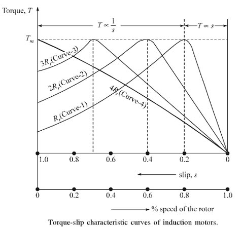
Ques 70. In the nodal analysis, for a network of N nodes, the number of the simultaneous equation to be solved to get the unknown is
- N
- N − 1✓
- N(N + 1)
- N(N − 1)
Nodal analysis is based on Kirchhoff’s current law which states that the algebraic sum of currents meeting at a point is zero. Every junction where two or more branches meet is regarded as a node. One of the nodes in the network is taken as the reference node or datum node. If there are n nodes in any network, the number of simultaneous equations to be solved will be (n- 1). Steps to be followed in Nodal Analysis
Ques 71. A solenoid Having N-turns and I ampere will have self-inductance of ______ Henry
- N/I
- -NΦ/I✓
- I/N
- IΦ/N
Self-Inductance When the current in a coil increases or decreases, there is a change in the magnetic flux linking the coil. Hence an e.m.f. is induced in the coil (called self-induced E.M.F ) which opposes the change of current in the coil (Lenz’s law). This phenomenon is called self-induction. The phenomenon of production of opposing e.m.f in a coil when the current through the coil changes is called self-induction. The self-induced e.m.f. opposes the change of current in the coil When the current passes along a wire and especially when it passes through a coil or inductor, a magnetic field is induced. This magnetic field extends outward from the wire or inductor and could couple with other circuits. However, it also couples with the circuit from which it is set up. Thus when the current in the coil is increasing the self-induced e.m.f is produced in the coil in such a direction so as to oppose the increase in current i.e. the self-induced e.m.f. acts in a direction opposite to that of the applied voltage V. When the current in the coil is decreasing the self-induced e.m.f. is produced in the coil in such a direction so as to oppose the decrease in current i.e., self-induced e.m.f. acts in the direction of applied voltage V. Self-inductance is measured in terms of the coefficient of self-inductance L. It obeys faraday’s law of electromagnetic induction like any other induced EMF. Thus self-inductance of a coil opposes the change of current (increase or decrease) through the coil. This opposition occurs because a changing current produces self-induced e.m.f. (es) which opposes the change of current. That is why the self-inductance of a coil is called electrical inertia of the coil. Expressions for self-inductance (L). We now find two equivalent expressions for self-inductance L of a coil (or circuit). (i) Consider a coil of N turns carrying a current I. Suppose the magnetic flux linked with each turn of the coil due to this current is Φ. Then the flux linkages with the coil will be NΦ. It is found that: NΦ ∝ I or NΦ = Ll where L is a constant of proportionality and is called the coefficient of self-induction or self-inductance of the coil. $L = – \dfrac{{N\Phi }}{I}$ Hence the coefficient of self-inductance of a coil is equal to the number of flux linkage with the coil when unit current is flowing through the coil. Units of self-inductance of a coil The S.I.unit of the coefficient of self-induction is Henry. If an emf of 1 volt is induced in a coil due to a change of current in it at the rate of I ampere/second, then the coefficient of self-induction of the coil is 1 Henry. Thus ${\text{1 Henry = }}\frac{{{\text{1 Volt}}}}{{1{\rm{ampere/sec}}}}$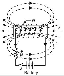
COEFFICIENT OF SELF INDUCTION (or SELF INDUCTANCE)
Ques 71. In the two wattmeter method of 3Φ power measurement, if the phase sequence of the supply is reversed
- The meter will not read
- One of the wattmeters will show the negative reading
- There won’t be a change in the meter reading
- The wattmeter will give an upscale reading✓
The reading of two wattmeters can be expressed as W1 = VLILcos(30 + φ) (i) When PF is unity ( φ = 0°) W1 = VLILcos30° Both wattmeters read equal and positive reading i.e upscale reading (ii) When PF is 0.5 (φ = 60°) W1 = VLILcos90° = 0 Hence total power is measured by wattmeter W2 alone (iii) When PF is less than 0.5 but greater than 0 i.e ( 90° > φ > 60°) W1 = Negative The wattmeter W2 reads positive (i.e.upscale) because for the given conditions (i.e. ( 90° > φ > 60°), the phase angle between voltage and current will be less than 90°. However, in wattmeter W1, the phase angle between voltage and current shall be more than 90° and hence the wattmeter gives a negative (i.e. downscale) reading. Wattmeter cannot show negative reading as it has only a positive scale. An indication of negative reading is that the pointer tries to deflect in a negative direction i.e. to the left of zero. In such a case, reading can be converted to positive by interchanging either pressure coil connections or by interchanging current coil connections. Remember that interchanging connections of both the coils will have no effect on wattmeter reading. (iv) When P.F reads zero (φ = 90°) Such a case occurs when the load consists of pure inductance or pure capacitance W1 = VLILcos(30 + 90°) = – VLILsin30° In this condition, the two wattmeter reads equal and opposite i.e W1 + W2 = 0
W2 = VLILcos(30 − φ)
W2 = VLILcos30°
W2 = VLILcos30°
W2 = positive (since cos(−φ) = cosφ)
W2 = VLILcos(30 − 90°) = VLILsin30°
Ques 72. When two alternators are in exact synchronism, their terminal voltage is
- In the opposite direction as compared to an external circuit
- Equal and in the same direction with regard to an external circuit✓
- Similar to an external circuit and local circuit
- Equal and in the same direction with regard to an armature
Synchronizing Current The alternator will run on synchronism after the proper synchronization of an alternator. A synchronizing torque will be developed if any of the alternators drops out of synchronism and will bring it back to the synchronism Consider the two alternators shown in Fig. which are in exact synchronism. Due to this, they are having the same terminal potential difference and with reference to their local circuit, they are in exact phase opposition. So there will not be any circulating current in the local circuit The emf E1 of alternator 1 is in exact phase opposition to that of alternator E2. With respect to an external load, the e.m.f s of the two alternators are in the same direction although they are in phase opposition win reference to the local circuit There will be no resultant voltage in the local circuit. Now assume that the speed of alternator 2 is changed such that it’s emf E2 falls by an angle α. But E1 and E2 are equal in magnitude. The resultant voltage Er, in this case, will cause a current in the local circuit which is called synchronizing current. This circulating current is Given by. ISY = Er ⁄ Zs Where Zs = Synchronous Impedance of the winding of an alternator.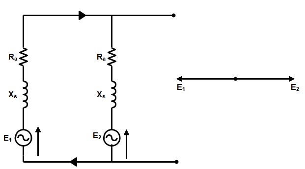
Ques 73. Power stations and sub-stations are protected against direct strokes of lightning using:
- Rod gap arrester
- Horn gap arrester
- Over Head ground wire
- Earthing screen✓
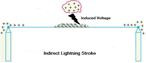
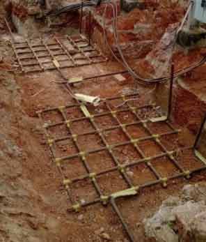
Types of Lightning Strokes There are two main types of lightning strokes that appear on various equipment in the power system. They are viz. Direct Stroke and Indirect Stroke. Direct stroke may appear on line conductor, on tower top, or on the ground wire indirect stroke may appear on overhead line conductors. Direct Stroke on Overhead Conductors These strokes are most dangerous as their effects are most severe and harmful. In this type of stroke, the discharge or the current path is directly from the cloud to the overhead line. From the line, the current path may be over the insulators down the pole to the ground. The voltage set up is in millions which can cause flashover and puncture of insulators. The insulators may get shattered till the surge is sufficiently dissipated and it travels to both sides. The wave may reach to the substation and damage the equipment because of excessive stress produced. The earthing screen and the ground wire provide protection against direct lightning strokes but do not provide any protection against travailing waves which may reach the electrical apparatus. The lightning arresters or the surge arresters are the ones who provide protection against the travailing waves. Indirect Strokes The effect of indirect strokes is similar to that of direct strokes. Their effect is more severe in the case of distribution lines than in the case of high voltage lines. These strokes are due to electrostatically induced charges on the conductors due to the presence of charged clouds. Sometimes currents may be induced electromagnetically due to lightning discharge in the immediate vicinity of the line which results in an indirect stroke. Commonly used equipment for protection against lightning strokes are as given below. To protect the generating stations and the substations from direct strokes, an earthing screen is used. Overhead ground wires protect the overhead transmission line from direct lightning strokes. The protection against both kinds of strokes direct and indirect in the form of travailing waves is provided with the help of lightning arresters. It consists of a network of copper conductors, earthed at least at two points, and overall the electrical equipment in the sub-station. When a direct stroke occurs on the station, the screen provides a low resistance path by which Lightning surges are conducted to the ground. In this way, station equipment is protected against damage. An Earthing Mat is the interconnection of the Horizontal and Vertical electrodes. The vertical Electrodes are for the dissipation of fault current into the ground while horizontal electrodes are laid for suppressing the dangerous Touch and Step voltages that are generated due to heavy fault current. A substation is an assembly of large no of electrical equipment. All the equipment, as well as working personnel, must be safe even in adverse conditions. The substation grounding system is an essential part of the overall electrical system. The proper grounding of a substation is important for the following two reasons: 1. It provides a means of dissipating electric current into the earth without exceeding the operating limits of the equipment. 2. It provides a safe environment to protect personnel in the vicinity of grounded facilities from the dangers of electric shock under fault conditions. The grounding system includes all of the interconnected grounding facilities in the substation area including the ground grid, overhead ground wires, neutral conductors, underground cables, foundations, deep well, etc. The ground grid consists of horizontal interconnected bare conductors (mat) and ground rods. The design of the ground grid to control voltage levels to safe values should consider the total grounding system to provide a safe system at an economical cost. After the construction of the Earth Mat, Crushed Gravels (of resistivity around 5000 ohms) are laid above the whole mat area. This makes the high resistive path for the dangerous voltages generated(Touch, Step Voltage), which in turn prevents a person from electric shock standing above the Earth mat area. There are some standards that guide the grounding of the substation. As per IEEE standards, earth mats are designed with vertical ground rods, and the earth mat brings down the overall resistance of the substation below 1 Ohm. The Earth mat spreads across the substation. All the equipment is connected to the earth mat with two separate earth flats. A good grounding scheme will ensure faster fault clearing and a low enclosure potential rise. The limitation of this method A that it does not provide protection against the traveling wave which may reach the equipment in the station.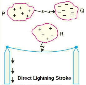
Earth Screening
Ques 74. The product of the demand factor and load factor is
- Average demand ⁄ Plant capacity
- Maximum Demand ⁄ Connected Load✓
- Station Energy Output ⁄ Plant capacity × hours of use
- Average demand ⁄ Maximum Demand
Demand Factor: The ratio of actual maximum demand on the system to the total rated load connected with the system is called the demand factor. $Demand{\text{ Factor = }}\dfrac{{{\text{Maximum Demand}}}}{{Co{\text{nnected Load}}}}$ Connected Load:– The sum of continuous rating of all the equipment which are connected to the supply system is called connected load. Maximum demand:– It is defined as the largest demand for the load on the generating station during a specified period. The load on the generating station is never constant but keeps on varying from time to time. The demand of load which is the maximum of all, during a given period, forms the maximum demand. Maximum demand is normally less than the connected load because the connected load to the system of various consumers is not switched on at the same time. The installed capacity of the station is decided by the maximum demand. It is quite obvious that the power station must be able to supply the maximum demand. Since the maximum demand is generally less than its connected load hence the demand factor is less than unity: the typical value ranges from 0.30 – to 0.90.
Ques 75. In the given circuit, the value of load resistance for which the power delivered is maximum is
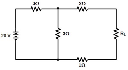
- 4.5 Ω✓
- 2 Ω
- 6 Ω
- 9 Ω
For Maximum Power to be transferred the Load Resistance RL and the internal Resistance Rth should be Equal. Rth = RL Thevenin’s resistance can be found by replacing the 20 V source with a short-circuit. As seen from Fig. , Rth = 1 + 2 + (3 || 3) = 4.5Ω. Hence the value of load resistance for which the power delivered is maximum is 4.5Ω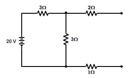
DMRC 2018 Solved Paper (9th April 2018) CLICK HERE
DMRC 2017 Solved Paper CLICK HERE
For NMRC 2017 Solved Paper CLICK HERE
DMRC 2016 Solved Paper CLICK HERE
For DMRC 2015 Solved Paper CLICK HERE
For DMRC 2014 Solved Paper CLICK HERE
For SSC JE CONVENTIONAL Paper 2017 CLICK HERE
For SSC JE CONVENTIONAL Paper 2016 CLICK HERE


Dear sir/Madam,
I am happy to express a grate atrebute to your website , for helping students by uploading previous question paper.
In this regard my hamble request you is to send soft copy of the these previous question paper to my email address so that it will be very helpful to me for further preparation.
I am ready to pay any charges required for it ( if any)
Hope. You don’t disappoint me
Regards
Vashista
9448351139