
The function of the emitter bypass capacitor in a CE amplifier is
Right Answer is:
Provide a low resistance path for the AC signals
SOLUTION
The function of the emitter bypass capacitor in a CE amplifier is to provide a low resistance path for the AC signals.
A common emitter (CE) amplifier is widely used in audio frequency applications in radio and television receivers. It provides current, voltage, and power gains. For the proper functioning of an amplifier, the transistor must be biased in the active region where the base current has complete control over the collector current. Thus a small increase in the base current results in a relatively large increase in the collector current and a small decrease in the base current is followed by a large decrease in the collector current.
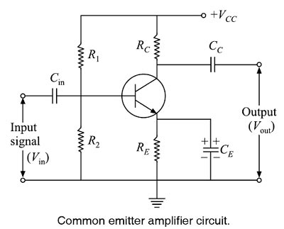
As shown in the Figure along with the transistor there are various RC components used to work the transistor as an amplifier. The functions of these components are as follows:
1. Biasing Circuit: Resistance R1, R2, and RE form the voltage divider biasing circuit for the CE amplifier. It sets the proper operating point and necessary biasing for the CE amplifier.
2. Input Capacitor Cin: This capacitor couples the signal to the base of the transistor. It blocks any dc component present in the signal and passes only A.C signal for amplification. Because of this biasing conditions are maintained constant.
3. Emitter Bypass Capacitor CE: A capacitor is connected in parallel across the emitter resistor RE called emitter bypass capacitor CE. The purpose of the bypass capacitor CE is to bypass the signal current to the ground. The ac signal (feedback voltage) developed across the emitter resistor RE is bypassed through the capacitor CE. Thus the gain of the amplifier increases, Since it provides an easy path to the ac emitter current and allows it to pass on instead of flowing through emitter resistor RE, hence the name emitter bypass capacitor.
If this capacitor is not put in the circuit, A.C emitter current will flow through RE causing an AC voltage drop across it. This voltage will produce a feedback effect and thereby reduce the output voltage. Thus, for proper amplification, an emitter bypass capacitor CE is essential.
The value of this capacitor is nearly 100 μF. However, if an amplifier is required to handle more than one frequency (i.e. composite frequency signal), then the value of the emitter bypass capacitor must be chosen that provides adequate bypassing for the lowest of all the frequencies. Then it will also be a good bypass for all the higher frequencies.
As a design guideline, we make the reactance of the capacitance CE at the lowest frequency not more than one-tenth the value of RE.
4. Output Coupling Capacitor Cc: The coupling capacitor Cc couples the output of the amplifier to the load or to the next stage of the amplifier. It blocks dc and passes Only AC part of the amplified signal.