
Ques.61. If a body reflect entire radiation incident on it, then it is known as
- Black body
- Gray body
- White Body
- Transparent Body
Answer.1. Black body Explanation:- A body that absorbs all the radiation incident on it would then appear ‘perfectly black’ to us. This is because we observe a body due to ‘reflection’ of radiation incident on it; and if a body absorbs all the radiation incident on it, then it would reflect no radiation. So, a body would be invisible to us or appear black to us. Such a body was called by Kirchhoff a black body. A body whose absorptive power is unity at all the wavelengths or that absorbs all incident electromagnetic radiation, regardless of frequency or angle of incidence is termed the black body
Ques.62. A digital timer in a resistance welding machine provides
- Accurate timing
- Identical welds
- Synchronous operation
- All of these
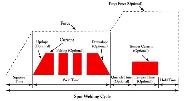
Answer.4. All of these Explanation:- The fig. Shows the resistance welding timer circuit, the welding machine receives ac power, by means of a timing device, through a power transformer, a circuit breaker, and an SCR or ignitron contactor. Inside the welding machine, a welding transformer reduces the voltage at the electrode tips (1 to 10 V) and supplies a large welding current, while drawing about 50 to 2000 A from the ac supply. The electrode tips are water-cooled and must be kept clean. A solenoid valve applies air pressure to the electrodes for bringing them together and squeezing the workpieces (metal pieces) properly. Welding current then flows to heat the workplace and make the weld. The workpiece is held under pressure for a few moments until the weld hardens. Then the electrodes separate so that the workpiece can be moved before the next weld is started. The resistance between the metal pieces decreases when they are forced together by the electrodes with greater pressure. To make a weld, the current needs to flow for only a fraction of a second. The ignitron contactor (these days SCR controlled circuits are used in place of line contactors) must close and open the circuit quickly, and it does these hundreds of times each hour. The timings of the welding process which may be divided into squeeze time, weld time, hold time, and OFF time, are controlled by a sequence timer. In the early days, the sequence weld timers could control the welding current. For the electrodes to come together and squeeze the jobs properly a solenoid valve is provided, which helps in creating the required pressure to hold the job pieces together. The jobs are held with high pressure between the electrodes and simultaneously high alternating current starts flowing intermittently as per the design of the switching circuit. The job pieces are properly heated and the welding takes place. The job after being held together during the welding for a definite period of lime, are set free as the electrodes separate from each other. The time period for which the jobs are held together under pressure is called the hardening time for the jobs. The timings of the welding process are controlled by a sequence timer as shown in the block diagram. The welding cycle may be divided into four successive sequences of time: squeeze time, weld time, hold time, and OFF time. The total timing sequence is Known as the timing of heat control of the welding process. All these four events are measured m a sequence by the sequence timer. After the welding machine is energized, the squeeze time duration allows the electrodes to grip the jobs properly and create the required amount of pressure on them. The weld time is the length of time during which the welding current is allowed to flow and the welding is performed. Hold time is the time during which the electrodes are allowed to continue to press the jobs even after the welding current has stopped flowing. This is allowed for the weld to harden and therefore is also known as the hardening time. After the weld is perfectly hardened, if the welding machine is still energized, the electrodes will reclose after a time period called the OFF time. This is a setting time that allows the job to be moved to a new position between the electrodes. If this is not required, the jobs may be taken out of the grips of the electrodes.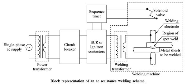
Ques.63. Which of the following generators are used in arc welding?
- Shunt generators
- Series Generator
- Cumulative compound generators
- Differential compound generators
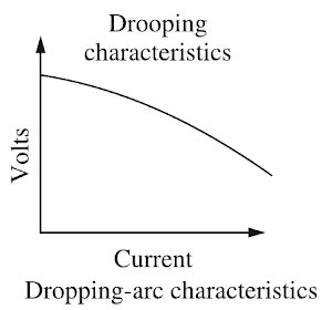
Answer.4. Differential compound generators Explanation:- Arc welding is the widely used method of joining metal parts. Here the source of heat is an electric arc. Arc welding is a group of welding processes wherein the heating is produced with an electric arc or arcs, mostly without the application of pressure and with or without the use of fillet metal, depending upon the base plate thickness. ARC Welding Principle In arc welding, the ARC is generated between the positive pole of D.C. (direct current) called the anode and the negative pole of D.C. called the cathode. When these two poles are brought together, and separated for a small distance (1.5 to 3 mm) such that the current continues to flow through a path of ionized particles, called plasma, an electric arc is formed. Since the resistance of this ionized gas column is high, so more ions will flow from the anode to the cathode. Heat is generated as the ions strike the cathode. A.C. or D.C. Machines in ARC Welding Depending upon the application, A.C. or D.C. machines are used in arc welding, but in some cases, either of them can be used. D.C. supply is usually obtained from generators driven by an electric motor or if no electricity is available then the diesel engine can be used. D.C. welding is mostly used for heavy work and at sites where electricity is not available. Arc welding requires a power source that can deliver electrical power at low voltage and high current such that it can establish and sustain an arc plasma column between the welding electrode and the workpiece. The line voltage in the mains supply is too high to be used directly in arc welding. Therefore either a transformer, solid-state inverter/rectifier or a motor-generator set is used to obtain the required open-circuit voltage necessary for arc welding. It is generally in the range of 20-80 V. At the same time, the same power source should be capable of delivering a high current typically ranging from 50 to 1500 A. This welding power source can have the output of alternating current (AC) or direct current (DC). These power sources have volt-ampere characteristics typically of constant current (CC) or constant potential (CP) type. The output may also have a pulsing mode. A schematic of the basic elements of an arc welding power source is shown in Fig. An arc behaves in a totally different manner from a norms resistance. As the current is increased the potential drop across the arc, instead of increasing as with an ohmic resistance, decreases up to a current of the order of 50-70 A, and then becomes approximately constant. This is because with increasing current arc increases in size, allowing a larger area for curve flow, and also increases in temperature becoming thereby more conducting. The generator used for welding purposes should have high current and low voltage which can be obtained by the differential compound generator. Differentially compounded DC generator has drooping characteristics that mean if load current increases the net flux will decreases(i.e shunt field and series fields in opposition will increases)due to demagnetization effect hence the Induced EMF and terminal voltage decreases.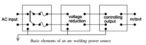
Ques.64. Which of the following is of high value in case of induction heating?
- Voltage
- Current
- Frequency
- All of the above
Answer.3. Frequency Explanation:- Induction heating is defined as the process of heating an electrically conducting object (usually a metal) by electromagnetic induction, through heat generated in the object by eddy currents. Induction heating occurs when an electrical current (eddy current) is induced into a workpiece. For the induction heating process to be efficient and practical, certain relationships of the frequency of the electromagnetic field that produces the eddy currents, and the properties of the workpiece, must be satisfied. The basic nature of induction heating is that the eddy currents are produced on the outside of the workpiece in what is often referred to as “skin effect” heating. Because almost all of the heat is produced at the surface, the eddy currents flowing in a cylindrical workpiece will be most intense at the outer surface, while the currents at the center are negligible. The depth of heating depends on the frequency of the ac field, the electrical resistivity, and the relative magnetic permeability of the workpiece. Frequency is one of the most critical parameters in these applications. If the frequency is too low, an eddy current cancellation within the heated body will take place, resulting in poor coil efficiency. However, when the frequency is too high, the skin effect will be highly pronounced, resulting in a current concentration in a very thin surface layer compared to the diameter/thickness of the heated component. In this case, a lengthy heating time will be required to provide sufficient heating of the internal areas and the core. Prolonged heat time results in an increase of the radiation and convection heat losses that, in turn, reduce the thermal efficiency of the induction heater and diminish the main advantage of induction heating. Frequency is always a reasonable compromise.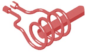
Ques.65. Induction heating process is based on
- Electromagnetic induction principle
- Resistance heating principle
- Thermal ion release principle
- Nucleate heating principle
Answer.1. Electromagnetic induction principle Explanation:- Induction heating is defined as the process of heating an electrically conducting object (usually a metal) by electromagnetic induction, through heat generated in the object by eddy currents. In induction heating when an alternating voltage applied to an induction coil (e.g., solenoid coil) will result in an alternating current in the coil circuit. An alternating coil current will produce in its surroundings a time-variable magnetic field that has the same frequency as the coil current. That magnetic field strength depends on the current flowing in the induction coil, the coil geometry, and the distance from the coil. The changing magnetic field induces eddy currents in the workpiece located inside the coil. These induced currents have the same frequency as the coil current; however, their direction is opposite to the coil current. Alternating eddy currents induced in the workpiece produce their own magnetic fields, which have opposite directions in the direction of the main magnetic field of the coil. Therefore, the total magnetic field of the induction coil is a result of the source magnetic field and induced magnetic fields. Alternating eddy currents produce heat by the Joule effect (I2R). A conventional induction heating system that consists of a cylindrical load surrounded by a multiturn induction, the coil is shown in Figure. In a narrow sense, induction heating is similar to the Joule heating effect, but with one important modification. The currents that heat the material are induced via electromagnetic induction. Therefore, it could be a non-contact heating process. Accordingly, only those with high electric conductivity, such as copper, gold, and aluminum, can be directly heated via induction. Food items are then heated by the metals. Induction heating works better on specific metals due to additional heating mechanisms. For instance, induction can heat ferrous metals better than other materials. That is because the iron crystals in ferrous metals can be repeatedly magnetized and demagnetized by the alternating magnetic field. This will lead to hysteresis losses in addition to the normal induction heating.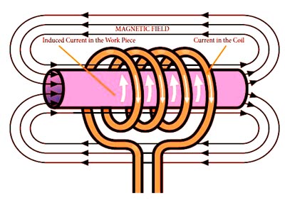
Ques.66. In case of induction hardening
- Heating occurs uniformly in the part to be heated
- Heating occurs in the core of the part to be heated
- Heating occurs in the center of the part to be heated
- Heating is more at the core and less on the surface of the part to be heated
Answer.1. Heating occurs uniformly in the part to be heated Explanation:- Because the heating is done by induction, this process is known as induction hardening. In induction hardening, rapid heating is generated by electromagnetic induction when a high-frequency current is passed through a coil surrounding the part. The depth to which the heated zone extends depends on the frequency of the current and the duration of the heating cycle. Because of an electrical phenomenon called “skin effect,” the depth of the heated area is inversely proportional to the frequency used. The time required to heat the surface layers to above the material transformation range is surprisingly brief, a matter of a few seconds. Selective heating and therefore hardening is accomplished by the suitable design of the coils or inductor blocks. At the end of the heating cycle, the steel is usually quenched by water jets passing through the inductor coils. Precise methods for controlling the operation, such as the rate of energy input, duration of heating, and rate of cooling, are thus necessary. These features are incorporated in induction hardening equipment, which is usually operated entirely automatically. Induction heating is an extremely versatile heating method that can perform uniform surface hardening, localized surface hardening, through hardening and tempering of hardened pieces. Heating is accomplished by placing a steel part in the magnetic field generated by high-frequency alternating current passing through an inductor, usually a water-cooled copper coil. The depth of heating produced by induction is related to the frequency of the alternating current: the higher the frequency is, the thinner or more shallow the heating. Therefore, deeper case depths and even through hardening are produced by using lower frequencies. Induction hardening offers a number of advantages over other heat treatment methods. The most important advantages are short heat treatment times, good repeatability concerning the hardened-layer quality, small or negligible subsequent distortion, and a minimum subsequent product surface oxidation. Induction Hardening
Ques.67. Induction heating, the depth upto which the current will penetrate is proportional to
- Frequency
- (Frequency)2
- 1/(Frequency)
- 1/(Frequency)1/2
Answer.4. 1/(Frequency)1/2 Explanation:- In induction heating, the heat in the electrically conducting workpiece is produced by circulating currents caused by electromagnetic induction. Induction heating is clean quick and efficient. It allows a defined section of the workplace to be heated accurately. The depth to which the heated zone extends depends on the frequency of the current and on the duration of the heating cycle. Because of an electrical phenomenon called “skin effect,” the penetration depth of the heated area is inversely proportional to the square root of frequency and directly proportional to the square root of the workplace resistivity p δ = K.√ρ/√f Where K is constant Therefore, the induction frequency is selected based on the application. A low frequency such as the utility frequency may be used for induction melting of large workpieces. High frequencies of up to a few hundred kilohertz are used for forging, soldering, hardening, and annealing.
Ques.68. The method of heating used in an electric room heat convector is
- Resistance heating
- Induction heating
- Dielectric heating
- Arc heating
Answer.1. Resistance heating Explanation:- RESISTANCE HEATING When the electric current is made to pass through a high-resistive body (or) substance, a power loss takes place in it, which results in the form of heat energy, i.e., resistance heating is passed upon the I2R effect. This method of heating has wide applications such as drying, baking of potteries, commercial and domestic cooking, and the heat treatment of metals such as annealing and hardening. In an oven where wire resistances are employed for heating, temperature up to about 1,000°C can be obtained. Electric resistance heaters all operate on the same principle as the resistance heating method. Current passes through a wire with high electrical resistance, generating heat in the process. The amount of heat generated depends on the wire resistance and the voltage. The resistance heating is further classified as: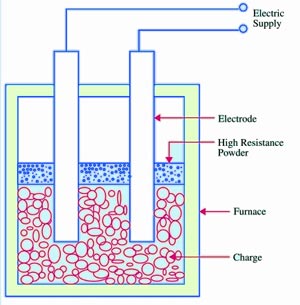
Ques.69. Highest power factor can be expected in which method of heating?
- Electric arc heating
- Dielectric heating
- Induction heating
- Resistance heating
Answer.4. Resistance heating Explanation:- Electric resistance heating converts nearly 100% of the energy in the electricity to heat. Resistance heating works equally well with low voltage and low-frequency supply. It works even on d.c. supply. In this method, all Be energy given to the resistance which acts as a heating element is converted to heat. The loss of energy occurs while transferring this heat from the element to the substance to be heated. Compared to other high-frequency methods this loss is the less thus overall efficiency of the resistance heating is high. One more advantage of resistance heating is it almost works on the unity power factor since it does not contain any inductive part. Resistance heating can be achieved in two ways direct resistance heating and indirect resistance heating.
Ques.70. Which of the following heating elements can give the highest temperature in resistance heating?
- Copper
- Nickel Copper
- Nichrome
- Silicon’s carbide
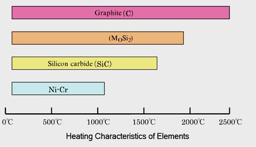
Answer.4. Silicon’s carbide Explanation:- Electrical heating elements in industrial furnaces are used in a variety of industries such as heat treatment of metals, electronic components, ceramics, and chemicals. Major Heating Elements ⇒ Ni-Cr-Based Heating Elements The Ni-Cr-based heating elements are typical metallic heating elements and are the most popular because they are inexpensive and easy to manufacture. Two types, one is composed of Ni 80% and Cr 20%, whereas the other is composed of Ni 60% and Cr 17% (plus Fe), are most widely used. The oxide film (Cr2O3) formed on the surface of the heating element functions as a protective film. ⇒MoSi2 (Molybdenum disilicide) Based Heating Element The MoSi2 (Molybdenum disilicide)based heating elements are made by forming a SiO2 (glass) film on the surface of MoSi2, a metallic material. The SiO2 film functions as a protective film, which enables usage of the element at high temperatures. Therefore, this metallic heating element can be used at high temperatures of up to 1,900°C under normal atmospheric conditions. However, the service temperature is lower under reducing atmospheres and high-vacuum conditions, in which the SiO2 film is degraded. The disadvantages of this element include brittleness at room temperature, low thermal shock and softening/deformation at high-temperature ranges. ⇒Silicon Carbide-Based Heating Element Non-metallic heating elements are represented by silicon carbide-based heating elements, which feature high thermal resistance and corrosion resistance. As for the electrical properties, they have negative characteristics upto approximately 600°C and positive characteristics at higher temperatures. The heating elements, with the maximum service temperature of 1,600°C, can be used over a versatile temperature range. The silicon carbide-based heating elements also have a SiO2 film that functions as a protective film generated on the surface, as in the case of MoSi2,-based heating elements. However, the resistance increases over time approaching the end of service life. ⇒Graphite Heating Element This heating element has a maximum service temperature of approximately 2,600°C in a non-oxidizing atmosphere such as in inert gas. However, the elements cannot be used in an oxidizing atmosphere because they react with oxygen and water vapor at temperatures above 400°C. The purity can be improved, allowing for the application to semiconductors. Furthermore, graphite-based heating elements are used not only for resistance heating but also for arc heating, and the demand for them as electrodes in steel manufacturing is high.

good
Nice
Knowledgeable
Its Usefull
Amazing mcq it is always help full of exams