
Ques.41. Which of the following statements is incorrect about the hot wire instruments?
- Their reading is independent of the wave form
- Their reading is independent of frequency
- They are unaffected by stray fields
- Their response is instantaneous.
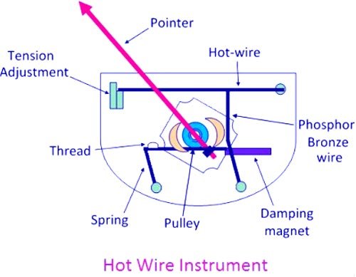
Answer.4. Their response is instantaneous. Explanation:- Working of the hot-wire instrument is based on the heating effect of electric currents. When the current to be measured passes through the hot wire, the wire gets heated and then expands. Since the wire is fixed between two points, it sags due to expansion which is magnified by the phosphor-bronze wire and silk thread. This expansion is taken up by the spring and the silk thread, which causes the pulley to rotate and the pointer is deflected. Deflecting Torque The deflection of the pointer of the hot-wire instrument is proportional to the extension of the hot wire, which is itself proportional to the square of the current. Hence Deflecting Torque. Td ∝ I2 If spring control is used, then Controlling torque Tc ∝ θ (deflection) For balanced condition TC = Td ∴ θ ∝ I2 Thus, these instruments have a square-law type scale. They read the r.m.s value of current and are independent of its frequency. Damping:- Damping is provided by a thin aluminum disc fixed to the spindle and moving between the poles of a permanent magnet. If there is any tendency to oscillate, eddy currents are set up in the disc and the direction of these current is such as to oppose the motion producing them. Adjustment is provided for the zero position Of the pointer by a spring moved by means of a screw at one end of the hot wire. These instruments are primarily meant for use as ammeters but can be used as voltmeters by connecting a high resistance in series with the instrument. These instruments are suited both for a.c. and d.c. work. Following are the advantages of hot-wire instruments: Hot-wire instruments are now obsolete and have been replaced by the more sensitive, more accurate and better-compensated combination of thermoelectric heating element and PMMC movement.Working Of Hot Wire Instrument
Advantages of Hot Wire Instrument
Disadvantages of Hot Wire Instrument
Ques.42. Which type of damping is generally preferred in case of instruments having a weak magnetic field?
- Air friction damping
- Fluid friction damping
- Eddy current damping
- Hysteresis damping
Answer.1. Air friction damping Explanation:- Air Friction Damping In this system, a light aluminum piston is attached to the spindle of the instrument and is arranged to move in a fix air chamber closed at one end. The cross-section of the chamber may be either circular or rectangular and the clearance between the piston and the side of the chamber is small and uniform. Compression and suction action of the piston on the air in the chamber damp the possible oscillations of the moving system because the motion of the piston in either direction is opposed by the air. It is used when the operating field is weak as used in moving iron and electro-dynamometer type instrument. Note:- Eddy Current Damping: It is used in a strong operating field. e.g., PMMC (Permanent Magnet Moving Coil instrument) type. Fluid Friction Damping: Used in high voltage measurement. Used in the vertically mounted instrument. e.g., Electrostatic type instrument.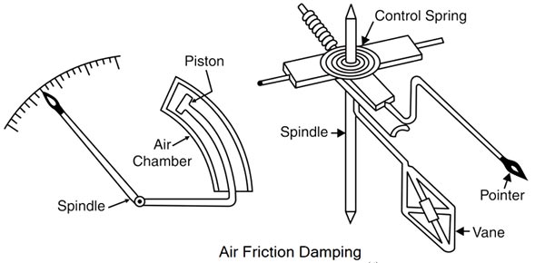
Ques.43. Voltmeter sensitivity is defined as
- Reciprocal of the full-scale deflection current
- Volts per ohm
- Ohms per volts
- Its degree of sensitiveness to impulse change
Answer.1. Reciprocal of the full-scale deflection current Explanation:- A voltmeter is an instrument used for measuring the electrical potential difference between two points in an electric circuit. Sensitivity: Sensitivity of an instrument indicates the capacity of the instrument to respond truly to the change in the output, corresponding to the change in the input. The sensitivity of a voltmeter is given in ohms per volt. It is determined by dividing the sum of the resistance of the meter (Rm) plus the series resistance (Rs), by the full-scale reading in volts. In equation form, sensitivity is expressed as follows: Sensitivity, S = (Rm + Rs) ⁄ Vin This is same as saying that the sensitivity is equal to the reciprocal of the full-scale deflection current. In equation form, this is expressed as follows: S = Ohm/Volt = 1/Amp = 1/Ifsd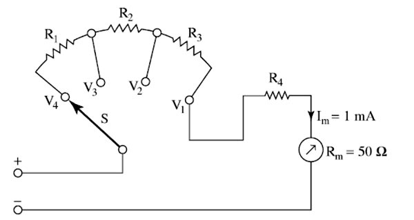
Ques.44. Power is being measured by two wattmeter method in a balanced three phase system. The wattmeter reading are
W1 = 250 kW
W2 = 50 kW
If the latter reading is obtained after reversing the connection to the current coil of W2, the power factor of the load is
- Unity
- 0.655
- 0.5
- 0.359
Answer.4. 0.359
Explanation:-
Reading of wattmeters
W1 = 250 kW
W2 = 50 kW
When the latter reading is obtained after the reversal of the current coil terminals of the wattmeter
W1 = 250 kW
W2 = −50 kW
Total power W = W1 + W2
W = 250 + (−50) = 200 W
The power factor of the two wattmeters is
tanØ = √3[(W1 – W2) / (W1 + W2)]
tanØ = √3[(200 – (−50)) ⁄ [250 + (−50)]
tanØ = √3[300/200]
Φ = 68.96°
Power factor = cosΦ = cos(68.96°) = 0.3590
Ques.45. Which of the following instrument is undesirable for measurement of AC values?
- Moving iron repulsion type
- Moving iron attraction type
- Dynamometer type
- The permanent magnet moving coil type
Answer.4. The permanent magnet moving coil type Explanation:- The PMMC type instrument can be used for measuring the DC value. Dynamometer type and Moving iron instrument can be used to measure the A.C and D.C
Ques.46. In which instrument the deflecting torque depends on the frequency
- Hotwire instrument
- Moving coil instrument
- Moving iron instrument
- Induction type instrument
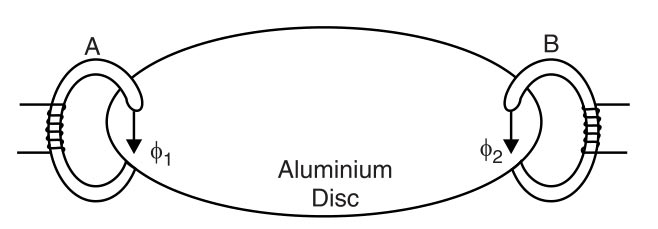
Answer.4. Induction type Instrument Explanation:- Induction type instruments are suitable only for a.c. measurements. These instruments may be used either as ammeter or voltmeter or wattmeter or energy meter. Perhaps the widest application of induction principle is in watt-hour or energy meter. The basic principle of induction type instruments is that when two alternating fluxes φ1 and φ2 (whose magnitudes depend upon the current or voltage to be measured having a phase difference θ pass through a metallic disc, usually of copper or aluminum. These alternating fluxes induce currents in the disc. The current produced by one flux reacts with the other flux, and vice-versa, to produce the deflecting torque that acts on the disc. It can be proved that net deflecting torque on the disc is given by; Td ∝ φ1m φ2m sinθ Since the magnitude of eddy currents also depend on the flux and frequency producing them, the instantaneous value of torque is proportional to the square of current or voltage under measurement and the value of mean torque is proportional to the mean square value of this current or voltage. Td ∝ I2 Advantages of Induction Instruments The following are the advantages of induction instruments: The following are the disadvantages of induction instruments: Errors In Induction Instruments Following are the errors in induction instruments: Error Due to Frequency Variation:- Variation of frequency directly affects the deflecting torque for a given current because the deflecting torque is directly proportional to the frequency. The value of impedance also varies with the change in frequency.Some compensation for frequency error can be provided by shunting the induction ammeter by the non-inductive shunt. Error Due to Temperature Variation: Since the resistance of the eddy current paths in the disc is dependent upon the temperature, it may produce serious errors. Compensation for temperature error is obtained by shunting the instrument in case of an ammeter with a shunt of the material having a higher temperature coefficient than that of aluminum of which the disc is made. In voltmeters, a combination of the shunt and swamping resistance is often used in series with the instrument.Induction type Instrument:-
Ques.47.The braking torque of induction type single-phase energy meter is:-
- Directly proportional to the square of the flux
- Directly proportional to the flux
- Inversely proportional to the flux
- Inversely proportional to the square of the flux
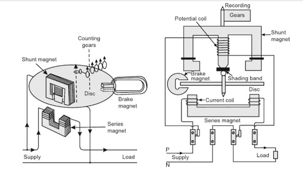
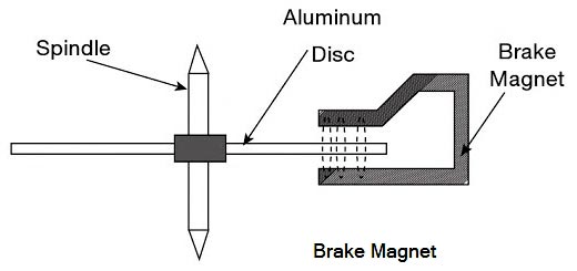
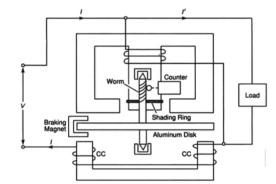
Answer.1. Directly proportional to the square of the flux Explanation:- An induction-type instrument can be used as an ammeter, voltmeter, or wattmeter, the induction-type energy meters are more popular. Induction-type single-phase energy meter is used invariably to measure the energy consumed in an AC circuit in a prescribed period where supply voltage and frequency are constant. The energy meter is an integrating instrument that measures the total quantity of electrical energy supplied to the circuit in a given period. Principle The basic principle of induction-type energy meter is electromagnetic induction. When AC flows through two suitably located coils (current coil and potential coil), they produce the rotating magnetic field that is cut by the metallic disc suspended between the coils, and thus, an emf is induced in the disc that circulates eddy currents in it. By the interaction of rotating magnetic field and eddy currents, electromagnetic torque is developed that causes the disc to rotate. This is the same principle that is applied in single-phase induction motors. A single phase energy meter has four essential parts: Operating System The operating system consists of two electromagnets. The cores of these electromagnets are made of silicon steel laminations. The coils of one of these electromagnets (series magnet) are connected in series with the load and are called the current coil. The other electromagnet (shunt magnet) is wound with a coil that is connected across the supply, called the pressure coil. The pressure coil, thus, carries a current that is proportional to supply voltage. Shading bands made of copper are provided on the central limb of the shunt magnet. Shading bands, as will be described later, are used to bring the flux produced by a shunt magnet exactly in quadrature with the applied voltage. Moving System The moving system consists of a light aluminum disc mounted on a spindle. The disc is placed in the space between the series and shunt magnets. The disc is so positioned that it intersects the flux produced by both the magnets. The deflecting torque on the disc is produced by an interaction between these fluxes and the eddy current they induce in the disc. In energy meters, there is no control spring as such, so that there is the continuous rotation of the disc. Braking System The braking system consists of a braking device which is usually a permanent magnet positioned near the edge of the aluminum disc. The arrangement is shown in Figure. The emf induced in the aluminum disc due to relative motion between the rotating disc and the fixed permanent magnet (brake magnet) induces an eddy current in the disc. When disc rotates in the air gap, eddy currents are induced in the disc which opposes the cause producing them i.e. relative motion of disc with respect to the magnet. This eddy current, while interacting with the brake magnet flux, produces a retarding or braking torque. This braking torque is proportional to the speed of the rotating disc. When the braking torque becomes equal to the operating torque, the disc rotates at a steady speed. The braking torque is proportional to the flux of the braking magnet and the eddy current induced in the moving system due to its rotation in the field of the braking magnet. TB ∝ φi where φ is the flux of the braking magnet and ‘i’ the induced current. Now i = e/R where e is the induced e.m.f. and R the resistance of the eddy current path. Also, e ∝ φn where n is the speed of the moving part of the instrument. ∴ TB ∝ φ × φn/R TB ∝ φ2n/R The position of the permanent magnet with respect to the rotating disc is adjustable. Therefore, braking torque can be adjusted by shifting the permanent magnet to different radial positions with respect to the disc. By changing the distance between braking magnet and magnetic shunt, the braking torque can be adjusted. The braking torque increases when the distance between them is increased because of moving the magnetic shunt away from the magnet, it will bypass a less amount of flux and vice versa. Hence the Braking torque provided by a permanent magnet is proportional to Registering System The function of a registering or counting system is to continuously record a numerical value that is proportional to the number of revolutions made by the rotating system.Induction-type Single-phase Energy Meter
Ques.48. Which of the following is the cause of the speed error in the induction type energy meter?
- Incorrect Position of brake magnets
- Incorrect adjustment of the position of shading bands
- Slow but continuous rotation of an aluminum disc
- Temperature variations
Answer.1. Incorrect Position of brake magnets
Explanation:-
The energy meter is an integrating meter which measures the electrical energy consumed by a load. Induction type energy meters are very commonly used to measure the electrical energy consumed in domestic, commercial and industrial installations.
Principle
The basic principle of induction type energy meter is electromagnetic induction. When alternating current flows through two suitably located coils (current coil and voltage coil), it produces the rotating magnetic field which is cut by the metallic disc suspended near to the coils. Thus, an emf is induced in the disc which circulates eddy currents in it.
Errors in induction type energy-meter
The following are the common errors which may creep in an energy meter:
- Phase and speed errors
- Frictional error
- Creeping error
- Temperature error
- Frequency error
Speed error:- Due to the incorrect position of the brake magnet, the braking torque not correctly developed. This can be tested when the meter runs at its full load current alternatively on loads of unity power factor and a low lagging power factor. The speed can be adjusted to the correct value by varying the position of the braking magnet towards the center of the disc or away from the center and the shielding loop. If the meter runs fast on inductive load and correctly on non-inductive load, the shielded loop must be moved towards the disc. On the other hand, if the meter runs slow on no inductive load, the brake magnet must be moved towards the center of the disc.
Phase Error:- The phase error is introduced because the shunt magnet flux does not lag behind the supply voltage by exactly 90° due to some resistance of the coil and iron losses. The angle of lag is slightly less than 90°. Because of this error, the torque is not zero at zero power factor of the load and Therefore, energy meter registers some energy even though the actual energy passing through the meter is zero at zero power factor.
In order to remove this error, the flux produced by the shunt magnet should be made to lag behind the supply voltage exactly by 90°. This is accomplished by adjusting the position of copper shading band provided on the central limb of the shunt magnet. An error on the fast side, under these conditions, can be eliminated by bringing the shading band nearer to the disc and vice versa.
Friction Error:- This error is introduced due to friction at the rotor bearing and in the register mechanism. Because of this error, an unwanted braking torque acts on the moving system and meter registers less energy than the actual energy passing through it.
This error is compensated by placing two short-circuited bands on the outer limbs of the shunt magnet. These bands embrace the flux contained in the two outer limbs of the shunt magnet. An emf is induced and the current circulates through them. This causes phase displacement between the enclosed flux and the main gap flux. As a result of this, a small driving torque is exerted on the disc solely by the pressure coil which compensates, the frictional torque. The amount of this corrective torque is adjusted by the variation of the position of the two bands and it should be just sufficient to overcome the frictional torque without actually rotating the disc at on-load.
Creeping Error:- The slow but continuous rotation of the energy meter when only the pressure coil is excited and no current is flowing through the current coil is called creeping. This error may be due to excessive friction compensation, excessive voltage supply, stray magnetic field, etc.
In order to prevent creeping at no-load, two holes of the same radius are drilled in the disc on the opposite side of the spindle. This causes sufficient distortion of the field to prevent continuous rotation. The disc remains stationary when one of the holes comes under one of the poles of the shunt magnet.
Temperature Error:- By the change of temperature, the parameters of the coils change slightly which introduces a small error in the meter. However, this error is negligible and there is no need to provide any means to eliminate this error.
Frequency Error:- Since the energy meters are used normally at the fixed frequency, therefore they are designed and adjusted to have a minimum error at declared supply frequency which is normally 50 Hz in India.
Ques.49.The range can be increased by using which of the following instrument?
- Energymeter
- Voltmeter
- Ammeter
- Current Transformer
Answer.4. Current Transformer Explanation:- Instrument transformers are used in conjunction with ammeter and voltmeter to extend the range of meters. In dc circuit shunt and multipliers are used to extend the range of measuring instruments. The shunt is used to extend the range of ammeter whereas multiplier is used to extend the range of voltmeters This type of ammeter is shown in Figure. The primary of the transformer is connected in series with the load, and the ammeter is connected to the secondary of the transformer. Notice that the range of the meter is changed by selecting different taps on the secondary of the current transformer. The different taps on the transformer provide different turns-ratios between the primary and secondary of the transformer. The working is explained in detail.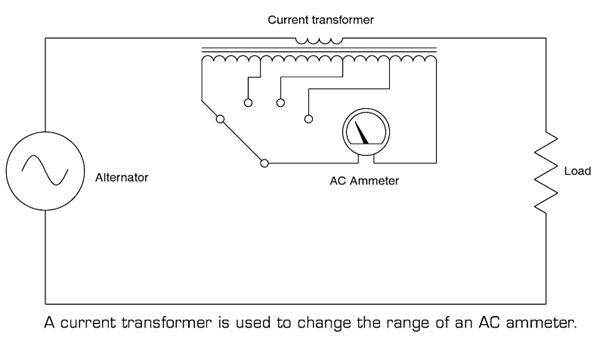
Ques.50. When the shunt resistance of the galvanometer circuit increased its
- Current sensitivity increases
- Current sensitivity decreases
- Damping increases
- Controlling torque decreases
Answer.2. Current sensitivity decreases Explanation:- A Galvanometer is an electromechanical instrument used for detecting and indicating an electric current of upto 10−9 A. A galvanometer is converted into an ammeter by connecting a suitable small resistance (called sum) in parallel with the galvanometer. For measuring current in a circuit, an ammeter is connected in series with the circuit. In order that the insertion of ammeter in the circuit does not affect the circuit current, it should have as low resistance as possible. So if the shunt resistance is increased the sensitivity of the galvanometer is decreased.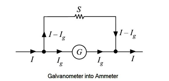
Good
Very good
Hi how r you great to see your important topics u share in this forum