100 Most Important MCQ Of Measurement and Instrumentation with explanation
8 Comments
/ MCQ / December 5, 2018 February 25, 2023
Ques.81. Which of the following instruments does not use the effect of current for measurement purposes?
Electrostatic Instrument
Hotwire Instrument
Rectifier Instrument
Moving coil Instrument
Answer.1.Electrostatic Instrument
Explanation:-
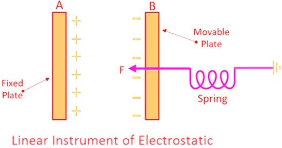
Electrostatic Instrument
These are the only instruments that are directly voltage-sensitive and do not depend on a current for their operation. Electrostatic instruments are almost always used as voltmeters and that too is more as a laboratory rather than as industrial instruments.
Operating Principle
The operating principle of an electrostatic instrument depends on the force of attraction between two or more electrically charged conductors between which a potential difference is maintained, and this force gives rise to a deflecting torque. The electrostatic mechanism resembles a variable capacitor, where the force existing between the two parallel plates is a function of the potential difference applied to them.
Basically, there are two types of electrostatic (also known as electrometers instruments):
(i) Quadrant type
(ii) Attracted-disc type
Advantages of Electrostatic Instruments
The following are the advantages of electrostatic instruments:
They can be manufactured with a very high accuracy.
They can be used on either a.c. or d.c. and over a fairly large range of frequencies.
The instruments may be calibrated with d.c, and yet the calibration would be valid for a.c. also since the deflection is independent of the waveform of the applied voltage.
Since no iron is used for their construction, they are free from hysteresis, eddy current losses and temperature errors.
Their power loss is negligible.
They are unaffected by stray magnetic field although they have to be guarded against any stray electrostatic field.
Once the discs are charged, no more current is drawn from the circuit and the instrument represents infinite impedance.
They can be used upto 1000 kHz frequency without any serious loss of accuracy.
They do not draw any continuous current on d.c. circuits and that drawn on d.c. circuits are extremely small. Hence, such voltmeters do not cause any disturbance to the circuit to which they are connected.
Limitations or Electrostatic Instruments
The following are the limitations of electrostatic instruments:
Their use is limited to certain special applications, particularly in a.c. circuits of relatively high voltage where the current taken by other instruments would result in erroneous indications.
Low voltage voltmeters are liable to friction errors.
Since the deflecting torque is proportional to the square of the voltage, their scales are not uniform although some uniformity can be obtained by suitably shaping the quadrants of the instruments.
They are expensive and are not likely to be durable.
They are, inherently, laboratory-type rather than industrial-type instruments.
82. Radio frequency can be measured by which of the following?
Weston Frequency meter
Vibrating reed vibrator
Heterodyne frequency Meter
Ferrodynamic frequency meter
Answer.3.Heterodyne frequency Meter
Explanation:-
A heterodyne frequency meter is an oscillator in which the tuning control is calibrated in terms of frequency. The oscillator used is stable and tuneable and depends upon the frequency range to be covered. It is desirable that the oscillator has a low-temperature coefficient of frequency, and that its frequency be insensitive to changes in the supply voltage. Good mechanical construction is also desirable. The oscillator of the heterodyne frequency meter must be isolated by a suitable buffer circuit arrangement so that its frequency is not affected by either the energy or the impedance of the circuits into which the frequency meter is connected when making measurements. When a heterodyne frequency meter is to be used for interpolation purposes, it is desirable that the frequency be linearly proportional to the angle of rotation of the tuning dial to a high degree of precision.
The accuracy of the frequency indicated by a heterodyne frequency meter is ordinarily greater than the accuracy of the corresponding lumped-circuit wavemeter. This is because an oscillator generates a definite frequency for any particular setting of its resonant tank circuit.
Applications:-
Heterodyne frequency meters are employed for such purposes
Producing known frequencies
Measuring an unknown frequency by comparison with the controllable an unknown frequency of the heterodyne frequency meter
For interpolation between known fixed frequencies.
Superheterodyne circuit found in almost all radio and television receivers, it is used in radio transmitters, modems, satellite communications and set-top boxes, radar, radio telescopes, telemetry systems, cell phones, cable television converter boxes and headends, microwave relays, metal detectors, atomic clocks, and military electronic countermeasures (jamming) systems.
Ques.84. One wattmeter method is used to measure power in a three-circuit when
The power factor is unity
The supply frequency is 50 Hz only
The load is balanced in all three phases
The supply voltages is 220 V
Answer.3.The load is balanced in all three phases
Explanation:-
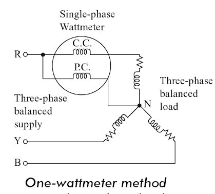
One-wattmeter Method
In this method, only one single-phase wattmeter can be used to measure the total three-phase power. this method, the current coil (CC) of the wattmeter is connected in series with any phase and the pressure coil (PC) is connected between that phase and the neutral as shown in Fig.
The one-wattmeter method has a demerit that even a slight degree of unbalance in the load produces a large error in the measurement. ln, this method one wattmeter will measure only the power of one phase. Hence, the total power is taken is three times the wattmeter reading.
Total Power = 3 × Vph. Iph. cosφ
Note:- The two and three-wattmeter methods can be used for balanced as well as unbalanced load.
A wattmeter is an instrument with a potential coil and a current coil so arranged that its deflection is proportional to VI cosθ, where V is the voltage (RMS value) applied across the potential coil, I is the current (RMS valued passing through the current coil, and θ is the angle between V and I.
In a three-phase system, total power is the sum of powers in three phases. The power is measured by the wattmeter. It consists of two coils. (i) current coil, and (ii) voltage coil. The current coil is connected in series with the load and it senses current. Voltage coil is connected across supply terminals and it senses voltages.
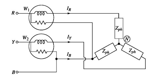
Two Wattmeter Method
This method is used for balanced as well as unbalanced load. The current coils of the two wattmeters are inserted in any two lines and the voltage coil of each wattmeter is joined to a third line. The load may be a star or delta connected. The sum of the two wattmeter readings gives three-phase power.
W = W1 + W2 = Three-phase
Ques.86. What could be the maximum reading on 3 -1/2 digit voltmeter?
1000
1111
1900
1999
Answer.4.1999
Explanation:-
Digital Multimeter
3 -1/2 digits of digital multimeter refer to the number of digits showed on the display of a digital multimeter. A 3 1/2 digits digital multimeter has three full digits that can change from 0 to 9 and the one-half digit that can change to either 0 or 1. That means 3 1/2 digits digital multimeter can show values from 0 to 1,999 (Max) or 0 to -1,999(min).
For example, a 6 -1/2 digit display has a 7-digit readout, but the most significant digit can read 0 or 1 while the other 6 digits can take any value from 0 to 9. Hence, the range of counts is ±1,999,999.
Ques.87. The resolution of a digital ammeter with 4 digit display is
1/10000
1/1000
1/4
1/40
Answer.1. 1/10000
Explanation:-
Resolution is the smallest change in input or measured variable which can be measured by an instrument. In digital meters, the resolution is determined by the number of digits used.
If n is the number of full active digits, then the resolution is defined as 1/10n
Thus, a four digits display will have a resolution of 1/104 = 1/10000
Ques.88. In two wattmeter method if the power factor is 0.5, then one of the wattmeters will read
Zero
W/2
W/√2
W/√3
Answer.1.Zero
Explanation:-
The reading of two wattmeters can be expressed as
W1 = VLILcos(30 + φ) W2 = VLILcos(30 − φ)
(i) When PF is unity ( φ = 0°)
W1 = VLILcos30° W2 = VLILcos30°
Both wattmeters read equal and positive reading i.e upscale reading
(ii) When PF is 0.5 (φ = 60°)
W1 = VLILcos90° = 0 W2 = VLILcos30°
Hence total power is measured by wattmeter W2 alone. Hence one of the wattmeter will read Zero.
(iii) When PF is less than 0.5 but greater than 0 i.e ( 90° > φ > 60°)
The wattmeter W2 reads positive (i.e.upscale) because for the given conditions (i.e. ( 90° > φ > 60°), the phase angle between voltage and current will be less than 90°. However, in wattmeter W1, the phase angle between voltage and current shall be more than 90° and hence the wattmeter gives negative (i.e. downscale) reading.
Wattmeter cannot show negative reading as it has the only positive scale. An indication of negative reading is that pointer tries to deflect in a negative direction i.e. to the left of zero. In such case, reading can be converted to positive by interchanging either pressure coil connections or by interchanging current coil connections. Remember that interchanging connections of both the coils will have no effect on wattmeter reading.
(iv) When P.F reads zero (φ = 90°)
Such a case occurs when the load consist of pure inductance or pure capacitance
In this condition, the two wattmeter reads equal and opposite i.e W1 + W2 = 0
Ques.89. A wattmeter is marked 15 A/30 A, 300 V/600 V and its scale is marked up to 4500 watts. When the meter is connected to 30 A, 600 V, the point indicated 2000 watts. The actual power of the circuit is
2000 watts
4000 watts
6000 watts
8000 watts
Answer.4.8000 watts
Explanation:
Power consumed by wattmeter = CT ratio x PT ratio x VIcosΦ……..1
In the above question
Power consumed by wattmeter = 2000 watts
CT ratio = 15 / 30
PT ratio = 300 / 600
VI = 600 x 30
Putting all the value in equation number 1 we get
2000=(15/30) x (300/600) x 600 x 30 x cosΦ
CosΦ = 0.4444
Power = VI cosΦ = 600 x 30 x 0.4444
Power = 7999.2 ≅ 8000 watts
Ques.90. Resistance is measured by the voltmeter ammeter method. The voltmeter reading is 50 V on 100 Volts scale and ammeter reading is 50 mA on 100 mA scale. If both the meter are guaranteed for accuracy within 2% of full scale, the limit within which resistance is measured will be
10Ω
20Ω
80Ω
40Ω
Answer.3.80Ω
Explanation:
Given Reading on voltmeter and ammeter is
V = 50 V
I = 50 mA
Resistance R = V/I = 50/50 × 10−3 = 1KΩ
Limiting error in voltmeterat full scale is
δE = ± 2% of 100
δE = ±2V
Thus when the reading is 50 V, the error will still be 2 V. Hence the % limiting error
= (2/50)x100 = 4%
Limiting error in ammeterat full scale is
δE = ± 2% of 100
δE = ±2mvA
Thus when the reading is 50mA, the error will still be 2mA. Hence the % limiting error

Good
Very good
Hi how r you great to see your important topics u share in this forum