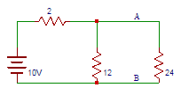
81. Consider the circuit shown below. Find the equivalent Thevenin’s voltage between nodes A and B.
A. 8
B. 8.5
C. 9
D. 9.5
Answer: B
Thevenin’s voltage is equal to the open-circuit voltage across the terminals AB that is across a 12Ω resistor.
Vth = 10×12/14 = 8.57V.
82. Consider the circuit shown below. Find Thevenin’s resistance between terminals A and B.
A. 1
B. 2
C. 1.7
D. 2.7
Answer: C
The resistance into the open circuit terminals is equal to the Thevenin’s resistance
= > Rth = (12×2)/14 = 1.71Ω.
83. Consider the circuit shown below. Find the current flowing through a 24Ω resistors.
A. 0.33
B. 0.66
C. 0
D. 0.99
Answer: A
The equivalent thevenin’s model of the circuit shown is
I = 8.57/(2.4 + 1.71) = 0.33A.
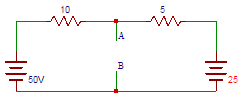
84. Determine the equivalent Thevenin’s voltage between terminals A and B in the circuit shown below.
A. 0.333
B. 3.33
C. 33.3
D. 333
Answer: C
Let us find the voltage drop across terminals A and B.
50 − 25 = 10I + 5I = > I = 1.67A.
Voltage drop across 10Ω resistor = 10×1.67 = 16.7V.
So, Vth = VAB = 50 − V = 50 − 16.7 = 33.3V.
85. Find the equivalent Thevenin’s resistance between terminals A and B in the circuit shown below.
A. 333
B. 33.3
C. 3.33
D. 0.333
Answer: C
To find Rth, two voltage sources are removed and replaced with a short circuit. The resistance at terminals AB then is the parallel combination of the 10Ω resistor and 5Ω resistor
= > Rth = (10×5)/15 = 3.33Ω.
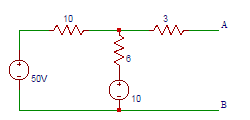
86. Determine the equivalent Thevenin’s voltage between terminals A and B in the circuit shown below.
A. 5
B. 15
C. 25
D. 35
Answer: C
Current through 3Ω resistor is 0A. The current through 6Ω resistor
= (50 − 10)/(10 + 6) = 2.5A.
The voltage drop across 6Ω resistor = 25×6 = 15V.
So the voltage across terminals A and B = 0 + 15 + 10 = 25V.
87. Find the equivalent Thevenin’s resistance between terminals A and B in the following circuit.
A. 6
B. 6.25
C. 6.5
D. 6.75
Answer: D
To find Rth, two voltage sources are removed and replaced with short circuit
= > Rth = (10×6)/(10 + 6) + 3 = 6.75Ω.
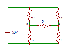
88. Determine the equivalent Thevenin’s voltage between terminals ‘a’ and ‘b’ in the circuit shown below.
A. 0.7
B. 1.7
C. 2.7
D. 3.7
Answer: C
The voltage at terminal a is
Va = (100×6)/16 = 37.5V,
The voltage at terminal b is
Vb = (100×8)/23 = 34.7V.
So the voltage across the terminals ab is
Vab = Va − Vb = 37.5 − 34.7 = 2.7V.
89. Find the equivalent Thevenin’s resistance between terminals A and B in the circuit shown below.
A. 6
B. 7
C. 8
D. 9
Answer: D
To find Rth, two voltage sources are removed and replaced with short circuit
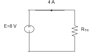
93. In the following circuit, when R = 0 Ω, the current IR equals to 10 A. The value of R, for which maximum power is absorbed by it is ___________
A. 4 Ω
B. 3 Ω
C. 2 Ω
D. 1 Ω
Answer: C
The Thevenin equivalent of the circuit is as shown below.
Therefore from the figure, we can infer that Rth = 2 Ω
94. In the following circuit, when R = 0 Ω, the current IR equals to 10 A. The maximum power will be?
A. 50 W
B. 100 W
C. 200 W
D. 400 W
Answer: A
The Thevenin equivalent of the circuit is as shown below.
I = 10 A, Rth = 2 Ω
∴ Pmax = (10/2)2 × 2
= 5×5×2 = 50 W.
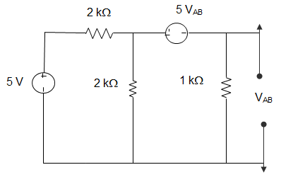
95. For the circuit given below, the Thevenin resistance across the terminals A and B is ________
A. 5 Ω
B. 7 kΩ
C. 1.5 kΩ
D. 1.1 kΩ
Answer: B
Let VAB = 1 V
5 VAB = 5
Or, 1 = 1 × I1 or, I1 = 1
Also, 1 = − 5 + 1(I – I1)
∴ I = 7
Hence, R = 0.2 kΩ.
96. For the circuit given below, the Thevenin voltage across the terminals A and B is ____________
A. 1.25 V
B. 0.25 V
C. 1 V
D. 0.5 V
Answer: D
Current through 1 Ω = (5/2) – I1
Using source transformation to 5 V sources
VOC = 1 × I1
VOC = − 5 VOC + (5/2) – I1) × 1
Eliminating I1, we get, VOC = 0.5 V.
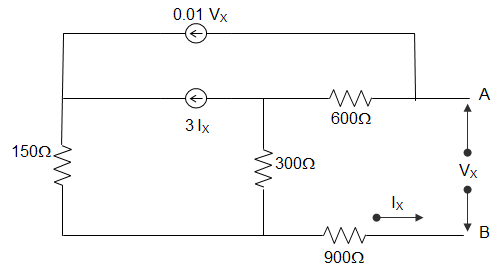
97. In the following circuit, the value of open-circuit voltage and the Thevenin resistance between terminals a and b are ________
A. VOC = 100 V, RTH = 1800 Ω
B. VOC = 0 V, RTH = 270 Ω
C. VOC = 100 V, RTH = 90 Ω
D. VOC = 0 V, RTH = 90 Ω
Answer: D
By writing loop equations for the circuit, we get,
VS = VX, IS = IX
VS = 600(I1 – I2) + 300(I1 – I2) + 900 I1
= (600 + 300 + 900) I1 – 600I2 – 300I3
= 1800I1 – 600I2 – 300I3
I1 = IS, I2 = 0.3 VS
I3 = 3IS + 0.2VS
VS = 1800IS – 600(0.01VS) – 300(3IS + 0.01VS)
= 1800IS – 6VS – 900IS – 3VS
10VS = 900IS
For Thevenin equivalent, VS = RTH IS + VOC
So, Thevenin voltage VOC = 0
Resistance RTH = 90Ω.
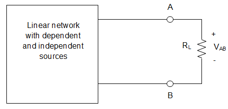
98. In the circuit given below, it is given that VAB = 4 V for RL = 10 kΩ and VAB = 1 V for RL = 2kΩ. The values of the Thevenin resistance and voltage for the network N are ____________
A. 16 kΩ and 30 V
B. 30 kΩ and 16 V
C. 3 kΩ and 6 V
D. 50 kΩ and 30 V
Answer: B
When RL = 10 kΩ and VAB = 4 V
Current in the circuit
I = VAB/RL = 4/10 = 0.4 mA
Thevenin voltage is given by
VTH = I (RTH + RL)
= 0.4(RTH + 10)
= 0.4RTH + 4
Similarly, for RL = 2 kΩ and VAB = 1 V
So, I = 1/2 = 0.5 mA
VTH = 0.5(RTH + 2)
= 0.5 RTH + 1
∴ 0.1RTH = 3
Or, RTH = 30 kΩ
And VTH = 12 + 4 = 16 V.
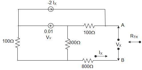
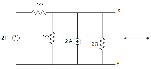
99. For the circuit shown in the figure below, the value of the Thevenin resistance is _________