RC Circuit Question and Answers – 2022

Ques.51. The expression of total impedance develop in the parallel RC circuit is

(1) ${Z = \left( {\frac{{R{X_C}}}{{\sqrt {{R^2} + {X^2}_C} }}} \right)\angle {{\tan }^{ – 1}}\left( {\frac{{{X_c}}}{R}} \right)}$


(2) ${Z = \left( {\frac{R}{{\sqrt {{R^2} + {X^2}_C} }}} \right)\angle {{\tan }^{ – 1}}\left( {\frac{R}{{{X_c}}}} \right)}$


(3)${Z = \left( {\frac{{R{X_C}}}{{\sqrt {{R^2} + {X^2}_C} }}} \right)\angle {{\tan }^{ – 1}}\left( {\frac{R}{{{X_c}}}} \right)}$


(4) ${Z = \left( {\frac{{R{X_C}}}{{\sqrt {{R^2} + {X^2}_C} }}} \right)\angle – {{\tan }^{ – 1}}\left( {\frac{R}{{{X_c}}}} \right)}$


Answer.4. ${Z = \left( {\frac{{R{X_C}}}{{\sqrt {{R^2} + {X^2}_C} }}} \right)\angle – {{\tan }^{ – 1}}\left( {\frac{R}{{{X_c}}}} \right)}$

Explanation:-

Parallel RC Circuit Impedance

Since there are only two circuit components, R and C, the total impedance can be expressed by the product-over-sum rule.

Parallel RC Circuit

${Z = \frac{{\left( {R\angle {0^^\circ }} \right)\left( {{X_C}\angle – {{90}^^\circ }} \right)}}{{R – j{X_C}}}}$


By multiplying the magnitudes, adding the angles in the numerator, and converting the denominator to polar form, we get

$Z = \frac{{\left( {R{X_C}} \right)\angle \left( {{0^^\circ } – {{90}^^\circ }} \right)}}{{\sqrt {{R^2} + {X^2}_C} \angle – {{\tan }^{ – 1}}\left( {\frac{{{X_c}}}{R}} \right)}}$


Now, by dividing the magnitude expression in the numerator by that in the denominator, and by subtracting the angle in the denominator from that in the numerator

$Z = \left( {\frac{{R{X_C}}}{{\sqrt {{R^2} + {X^2}_C} }}} \right)\angle \left( { – {{90}^^\circ } + {{\tan }^{ – 1}}\left( {\frac{{{X_c}}}{R}} \right)} \right)$


Equivalently, this expression can be written as

${Z = \left( {\frac{{R{X_C}}}{{\sqrt {{R^2} + {X^2}_C} }}} \right)\angle – {{\tan }^{ – 1}}\left( {\frac{R}{{{X_c}}}} \right)}$


Ques.52. For the RC Parallel determine the magnitude and phase angle of the total impedance when the resistance is 100Ω, capacitive reactance is 50Ω and the source voltage is 5V.

  1. 4.47 ∠−63.4°Ω
  2. 44.7 ∠−63.4°Ω
  3. 4.47 −6.34°Ω
  4. 40.7 −60.3°Ω

Answer.2. 44.7 ∠−63.4°Ω

Explanation:-

For the Parallel RC circuit, the total Impedance is

$\begin{array}{l} Z = \left( {\frac{{R{X_C}}}{{\sqrt {{R^2} + {X^2}_C} }}} \right)\angle – {\tan ^{ – 1}}\left( {\frac{R}{{{X_c}}}} \right)\\ \\ \\ = \frac{{(100)(50)}}{{\sqrt {{{(100)}^2} + {{(50)}^2}} }}\angle – {\tan ^{ – 1}}\left( {\frac{{100}}{{50}}} \right) \end{array}$

= 44.7 ∠−63.4°Ω


Ques.53. For the RC Parallel circuit shown in the figure, determine the magnitude and phase angle of the total impedance.

rc.img .11

  1. 8.94∠−26.6°Ω
  2. 894∠26.6°Ω
  3. 894∠−26.6°Ω
  4. 8.94∠26.6°

Answer.3. 894∠−26.6°Ω

Explanation:-

From the given figure

Resistance = 1 kΩ

Inductance = 2 kΩ

$\begin{array}{l} Z = \left( {\frac{{R{X_C}}}{{\sqrt {{R^2} + {X^2}_C} }}} \right)\angle – {\tan ^{ – 1}}\left( {\frac{R}{{{X_c}}}} \right)\\ \\ \\ = \frac{{(1)(2)}}{{\sqrt {{{(1)}^2} + {{(2)}^2}} }}\angle – {\tan ^{ – 1}}\left( {\frac{1}{2}} \right) \end{array}$


Z = 894∠−26.6°Ω


Ques.54. For parallel RC circuits, the phasor expression for Conductance (G) is

  1. G∠90°
  2. G∠180°
  3. G∠−90°
  4. G∠0°

Answer.4. G∠0°

Explanation:-

The conductance, G, is the reciprocal of resistance. The phasor expression for conductance is expressed as

G = 1/R∠0° = G∠0°


Ques.55. For parallel RC circuits, the phasor expression for inductive susceptance (BC) is

  1. jBC
  2. −jBC
  3. 2jBL
  4. None of the above

Answer.1. jBC

Explanation:-

Capacitive susceptance (BC) is the reciprocal of capacitive reactance. The phasor expression for capacitive susceptance is

BC = 1/XC∠−90°

BC = ∠90° = jBC


Ques.56. For parallel RC circuits, the phasor expression for Admittance (Y) is

  1. Y∠θ
  2. Y∠−θ
  3. Y∠2θ
  4. Y∠±θ

Answer.4. Y∠±θ

Explanation:-

Admittance (Y) is the reciprocal of impedance. The phasor expression for admittance is

Y = 1/Z∠ ±θ

Y = ∠ ±θ


Ques.57. For parallel RC circuits, the phasor expression for total Admittance (Y) of the circuit is

(1) $Y = \sqrt {{G^2} – {B^2}_C} $


(2) $Y = \sqrt {{G^2} + {B^2}_C} $


(3) $Y = \sqrt {{G^2} + 2{B^2}_C} $


(4) None of the above


Answer.2. $Y = \sqrt {{G^2} + {B^2}_C} $

Explanation:-

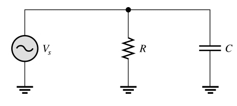
In working with parallel circuits, it is often easier to use conductance (G), capacitive susceptance, and admittance (Y) rather than resistance (R), capacitive reactance and impedance (Z).

In a parallel RC circuit, as shown in Figure a, the total admittance is simply the phasor sum of the conductance and the capacitive susceptance.

RC parallel circuit

Y = G + jBC

$Y = \sqrt {{G^2} + {B^2}_C} $


Ques.58. Determine the total admittance of the RC parallel circuit when the resistance is 330Ω, capacitance is 0.22μF  and the frequency is 1 kHz.

  1. 30.3 + j1.38
  2. 3.03 − j1.38
  3. 3.03 + j1.38
  4. 30.3 − j1.38

Answer.3. 3.03 + j1.38

Explanation:-

Resistance R = 330Ω

Conductance = 1/R = 1/330 = 3.03 mS.

Now Capacitive reactance

Xc = 1/2πfC

XC = 1/2π × 1000 × 0.22 = 723 kΩ

Capacitive Suspectance

BC = 1/XC = 1/723 = 1.38 mS.

The total Admittance is

Yt = G + JBC

Yt = 3.03 + j1.38


Ques.59. Determine the total impedance of the RC parallel circuit in polar form when the resistance is 330Ω, capacitance is 0.22μF  and the frequency is 1 kHz.

  1. 300∠24.5° mS
  2. 30.0∠24.5° mS
  3. 300∠−24.5° mS
  4. 30∠−24.5° mS

Answer.3. 300∠−24.5° mS

Explanation:-

Resistance R = 330Ω

Conductance = 1/R = 1/330 = 3.03 mS.

Now Capacitive reactance

Xc = 1/2πfC

XC = 1/2π × 1000 × 0.22 = 723 kΩ

Capacitive Suspectance

BC = 1/XC = 1/723 = 1.38 mS.

The total Admittance is

Yt = G + JBC

Yt = 3.03 + j1.38

Converting to polar form

$\begin{array}{l} {Y_t} = \sqrt {{G^2} + {B^2}_C} \angle – {\tan ^{ – 1}}\left( {\frac{{{B_c}}}{G}} \right)\\ \\ = \sqrt {{{(3.03)}^2} + {{(1.38)}^2}} \angle – {\tan ^{ – 1}}\left( {\frac{{1.38}}{{3.03}}} \right) \end{array}$


Now total impedance

Zt = 1/Yt

Zt = 1/(3.03 + j1.38)

Zt = 300∠−24.5° mS


Ques.60. Determine the total current of parallel RC circuit  as shown in the figure below

rc.img .12

  1. 50∠°−24.5° mA
  2. 50∠24.5° mA
  3. 500∠−24.5° mA
  4. 5∠24.5° mA

Answer.4. 5∠24.5° mA

Explanation:-

Resistance R = 330Ω

Conductance = 1/R = 1/2.2 = 455 µS.

Now Capacitive reactance

Xc = 1/2πfC

XC = 1/2π × 1.5 × 0.022 = 4.82 kΩ

Capacitive Suspectance

BC = 1/XC = 1/4.82 = 207 µS.

The total Admittance is

Yt = G + JBC

Yt = 455 + j207

Converting to polar form

$\begin{array}{l} {Y_t} = \sqrt {{G^2} + {B^2}_C} \angle – {\tan ^{ – 1}}\left( {\frac{{{B_c}}}{G}} \right)\\ \\ = \sqrt {{{(455)}^2} + {{(207)}^2}} \angle – {\tan ^{ – 1}}\left( {\frac{{207}}{{455}}} \right) \end{array}$

Yt = 500∠24.5° mS

Use Ohm’s law to determine the total current.

Itot = Vs.Yt

Itot = (10∠0°)(500∠24.5°)

Itot = 5∠24.5° mA

Scroll to Top