Ques 11. The power input to a 3-phase, 50 Hz, 400 V, the 4-pole induction motor is 60 kW and its stator losses are 1 kW. If this motor is running at 4% slip, the rotor copper loss is
1.18 kW
2.36 kW✔
0.18 kW
0.36 kW
Air gap power Pg
Pg = PInput – stator Loss
Pg = 60 – 1 = 59 kW
Rotor copper loss = Spg
= 0.04 x 59 = 2.36 kW
Ques 12. In a transformer, the core loss is found to be 46 W at 50 Hz and is 80 W at 70 Hz, both losses being measured at the same peak flux density. The hysteresis loss and eddy current loss at 60 Hz is
11 W, 20 W
30 W, 45 W
16 W, 30 W
22 W, 40 W✔
Core loss = Eddy current loss + Hysteresis loss
= Kef2 + Kcf
At 50 Hz, Pc = 46 watt
46 = Ke (50)2 + Kh x 50………. 1
At 70 Hz, Pc = 80 watt
70 = Ke (70)2 + Kh x 70…………… 2
From equation (1) and (2),
Ke = 0.0111
Kh = 0.363
Now at 60 Hz,
Pe = Ke x 602
= 0.0111 x 3600 = 39.96 ≅ 40 Watt
Ph = 0.36306 x 60
= 21.78≅ 22 Watt
i= I cos (ωt + θ)
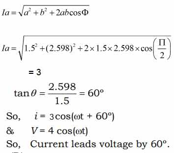
Ques 13. The voltage wave given by V = 4cosωt produces a current wave i = 1.5cosωt – 2.598sinωt in a circuit. The current wave
Leads voltage wave by 60°✔
Lags voltage wave by 60°
Leads voltage wave by 30°
Lags voltage wave by 30°
Given,
V = 4cosωt
i = 1.5cosωt – 2.598sinωt
= 1.5cosωt + 2.598sin(ωt + π/2)
Or I = Ia(cosωt + θ)……………(sinusoidal current wave)
Where Ia is amplitude or peak value of current which is given as
Ques 14. The effective damping in D Arsonval galvanometer is obtained by
A shunt connected across moving coil✔
Eddy current induced in metal discs
Fluid Friction
Employing springs
The use of a D-Arsonval galvanometer is very common in a variety of measuring instruments. The galvanometer is basically used in an instrument for detecting the presence of small voltages or currents in a circuit or to indicate zero current in applications lilts bridge circuits. Thus galvanometer has to be very much sensitive.
Damping: The damping is eddy current damping. The eddy currents developed in the metal former on which the coil is mounted, are responsible to produce damping torque. For effective damping, low resistance is connected across the galvanometer terminals. By adjusting the value of this resistance damping can be changed and critical damping can be achieved.
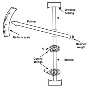
Ques 15. If θ represents deflection of the pointer, the controlling torque in a spring-controlled indicating instrument is proportional to
θ✔
θ2
1/θ
Sinθ
In indicating instrument the controlling torque, also called a restoring or balancing torque is obtained by two methods
Spring control Method
Gravity control Method
Spring Control Method
The springs used in measuring instruments for providing the controlling torque must have the following properties.
These should be of non-magnetic material.
Specific resistance should be low.
The resistance temperature coefficient should be low.
These should not be affected much by mechanical fatigue.
Phosphor Bronze is the most suitable for the springs of an indicating instrument as it satisfies most of the above properties. ln this method, two spiral hairsprings are used and spiraled in opposite directions. The use of two springs also avoids error due to temperature variations. One end of both the springs is attached to the body of the instrument and another end is attached to the moving system.
When the instrument is not in use, the two springs are in their natural position without any tension or compression( deflecting torque = Controlling Torque). When the instrument is connected to the circuit for the measurement, deflecting torque acts, and the pointer moves on the calibrated scale. One of the springs is unwound while the other gets twisted. The resultant movement in the springs provides the controlling torque.
More the deflection more is the twist and hence greater will be the controlling torque. Thus the controlling torque is directly proportional to the deflection of the moving system, i.e.,
Tc ∝ θ
And it is also clear that the pointer comes to rest when controlling torque becomes numerically equal to deflecting torque i.e
Tc = Td
But the deflection or the deflection torque depends upon the current flowing through it, hence
I ∝ θ
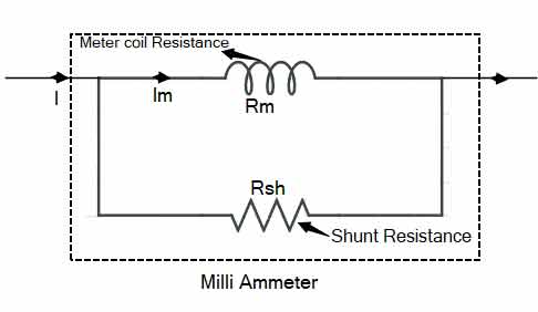
Ques 16. The range of a DC milliammeter can be extended by using a
Low resistance in series
Low resistance shunt✔
High resistance in series
High resistance shunt
The Range of the DC milliammeter can be extended by using resistance in parallel. The shunts are low resistances used in ammeters for range extension. The shunt is made of Manganin or Constantan depending on whether it is used for DC or AC.
With Im as the current flow through the meter capable of producing the maximum deflection, precautions are to be taken to ensure that the current through the meter coil is limited to Im. However, when the current to be measured is large, the alternative path is provided via, the low resistance shunt Rsh.
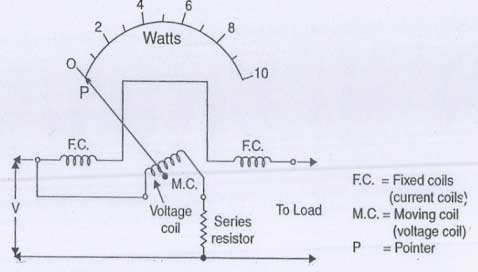
Ques 17. For use in AC circuits, the potential coil circuit of the electrodynamic wattmeter should be purely
Resistive✔
Inductive
Capacitive
Reactive
Electrodynamic Wattmeter
The electrodynamic Wattmeter consists of a pair of fixed coils, known as current coils, and a movable coil known as the potential coil. The fixed coils are made up of a few turns of a comparatively large conductor. The potential coil consists of many turns of fine wire. The current coils are connected in series with the circuit, while the potential coil is connected in parallel.
When line current flows through the current coil of a wattmeter, a field is set up around the coil. Since for AC power, current and voltage may not be in phase, owing to the delaying effects of circuit inductance or capacitance. Therefore the potential coil of the wattmeter generally has a high-resistance resistor connected in series with it. This is for the purpose of making the potential-coil circuit of the meter as purely resistive as possible. As a result, the current in the potential circuit is practically in phase with line voltage.
Ques 18. A DC shunt generator builds up 230 V when driven in the clockwise direction. In case it is driven in anti-clockwise direction, other things remain unchanged, then the voltage build-up is
Zero✔
230 V with brush polarity same
Somewhat less than 230 V with brush polarity reversed
Somewhat less than 230 V with brush polarity same
In case of DC shunt generator if we reverse the rotation there is no voltage build-up.When we rotate the generator in the reverse direction, flux due to residual magnetism will be canceled out and hence generator will not get sufficient initial flux for emf to build up.
Ques 19. A 100 kVA single phase transformer exhibits maximum efficiency at 80% of full load and the total loss in the transform under this condition is 1000 W. The ohmic losses at full load will be
781.25 watt✔
1250 watt
1562.5 watt
12500 watt
At maximum efficiency
Core loss = Copper loss
i.e Pc = Pcu
Total loss = Pc + Pcu = 1000 watt
Pcu = 500 watt
Copper loss = X2x Copper loss at full load
Where
X stands for loading condition of transformer
at 80% of the full load then Pcu at full load
Pcu = 500/0.82 = 781.25 watt
Ques 20. In a 3-phase induction motor hums during starting up, the probable cause could be
Unequal stator phase resistance
Open circuited rotor.
Inter turn short circuit on rotor✔
Any of the above
The inter-turn short circuit of the windings inside the rotor is a common electrical fault for the 3-phase induction motor. Bad manufacturing and assembling, overheating due to the jam in the windings, al also long-term stresses and vibrations may result in this fault. It may intensify the vibrations, burn the windings, and even lead to earth.
An inter-turn short circuit fault mainly causes the rotor to vibrate at fr (the rotating frequency of the rotor), while the static air-gap eccentricity fault primarily produces vibrations at 2fr and the combined fault generates vibrations at fr, 2fr, and 3fr at the same time which causes humming in an induction motor.


sir i would like to get more questions concerning transformer and induction motor plz
hello @Allon Y Allon ..definitely I will update more question of transformer and induction motor
thank you sir .please upload more more question
hello suryadey there are 6 set ssc je 2018 with full explanation and all ssc paper from 2009-2018 check out
sir question no 5 explaination can’t understand….please explain it easyly
Nice job sir ..it is very helpful