In such recording Instruments, the readings are recorded by drawing the graph. The pointer of such instruments is provided with a marker i.e. pen or pencil, which moves on graph paper as per the reading. The X-Y plotter is the best example of such an instrument.
X-Y recorders are used for many measurements and tests as follows:-
Speed/torque measurements of electric motors.
Lift/drag wind-tunnel tests.
Plotting of characteristic curves of vacuum tubes, transistors, rectifiers, zoner diodes, etc.
Measurement of physical quantities, such as force, pressure, temperature, etc.
Regulation curves of the power supply.
Electrical characteristics of materials such as resistance vs. temperature
Characteristics of governors, such as speed vs. load.
Note:- Ammeter, Voltmeter, Meggar all are Indicating Instrument
Hence when the power factor is more than 0.5 but less than one, both me wattmeters give positive (upscale) readings. However, wattmeter W1 gives larger reading than wattmeter W2.
Now, total power, P = W1 + W2 = larger reading + smaller readings
(iv) When PF is less than 0.5 but greater than 0 i.e ( 90° > φ > 60°)
The wattmeter W2 reads positive (i.e.upscale) because for the given conditions (i.e. ( 90° > φ > 60°), the phase angle between voltage and current will be less than 90°. However, in wattmeter W1, the phase angle between voltage and current shall be more than 90° and hence the wattmeter gives a negative (i.e. downscale) reading.
Wattmeter cannot show a negative reading as it has only a positive scale. An indication of negative reading is that the pointer tries to deflect in a negative direction i.e. to the left of zero. In such case, reading can be converted to positive by interchanging either pressure coil connections or by interchanging current coil connections. Remember that interchanging connections of both the coils will have no effect on wattmeter reading.
(v) When P.F reads zero (φ = 90°)
Such a case occurs when the load consist of pure inductance or pure capacitance
In this condition, the two wattmeter reads equal and opposite i.e W1 + W2 = 0
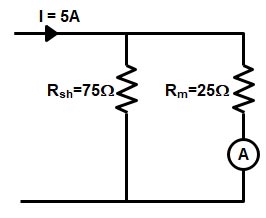
Ques.44. A resistance of 75 Ohms is connected in shunt of a galvanometer, having an internal resistance of 25 Ohms, to convert it into an ammeter. What is the value of current (in A) flowing through the galvanometer, if the total current in the circuit is 5 A?
2
2.5
3.65
3.75✓
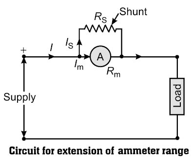
Extension of Ammeter Range
The current range of a DC moving coil ammeter is extended by connecting a shunt resistance Rs (low resistance) across the coil, the circuit as shown in Figure
I = Total current = 5A Im = full-scale deflection current of ammeter = ? Ish = shunt current Rm = resistance of the ammeter = 25Ω Rsh = shunt resistance = 75Ω
Ques.45. Which of the following is TRUE about analog multimeter?
It is a type of absolute instrument
It is a type of indicating instrument.✓
It is a type of recording instrument.
It is a type of integrating instrument.
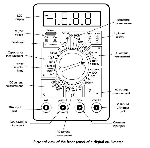
A multimeter is an indicating electronic instrument that can be used for the measurement of three quantities, namely voltage, current, and resistance. This instrument can also be used for both dc and ac voltages and currents. Multimeters are available in both analog and digital forms. Although analog multimeters are being replaced by digital multimeters.
Ques.46. The circuit given below is of a circuit _________ bridge.
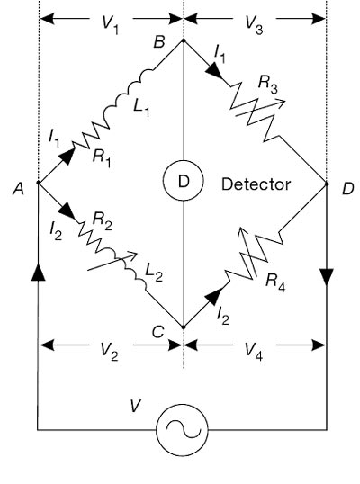
This bridge is used to measure the value of an unknown inductance by comparing it with a variable standard self-inductance. The bridge configuration and phasor diagram under-balanced conditions are shown in Figure
The unknown inductor L1 of resistance R1 in the branch AB is compared with the standard known inductor L2 of resistance R2 on arm AC. The inductor L2 is of the same order as the unknown inductor L1. The resistances R1, R2, etc., include, of course, the resistances of contacts and leads in various arms. Branch BD and CD contain known non-inductive resistors R3 and R4respectively.
The bridge is balanced by varying L2 and one of the resistors R3 or R4. Alternatively, R3 and R4 can be kept constant, and the resistance of one of the other two arms can be varied by connecting an additional resistor.
Under the balanced condition, no current flows through the detector. Under such conditions, currents in the arms AB and BD are equal (I1). Similarly, currents in the arms AC and CD are equal (I2).
Under the balanced condition, since nodes B and D are at the same potential, voltage drops across arm BD and CD are equal (V3 = V4); similarly, the voltage drop across arms AB and AC are equal (V1 = V2).
At the balanced condition
R1/R2 = R3/R4 = L1/L2
[/bg_collapse]
Ques.47. Which of the following materials when used as the viewing surface of a CRO gives a reddish glow?
Zinc Sulfide with copper as an impurity
Zinc Sulfide with silver as an impurity
Yttrium Oxide✓
Pure Zinc Sulfide
The actual conversion of electrical to light energy takes place on the display screen when electrons strike a material known as a phosphor. A phosphor is a chemical that glows when exposed to electrical energy.
The selection of phosphors to be used in a cathode ray tube is very important. Many different phosphors are known, and each has special characteristics. For example, the phosphor known as yttrium oxide gives off a red glow when struck by electrons, and yttrium silicate gives off a purplish-blue glow.
Zinc sulfide with silver metal as an impurity gives off a bluish glow and with copper metal as an impurity, agreenish glow.
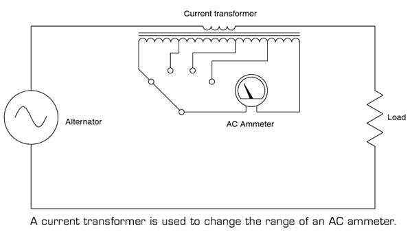
Ques.48. Which of the following is TRUE about current transformers?
It decreases the range of AC ammeter
It decreases the range of DC ammeter
It increases the range of AC ammeter✓
It increases the range of DC ammeter
Instrument transformers are used in conjunction with an ammeter and voltmeter to extend the range of meters. In dc circuit shunt and multipliers are used to extend the range of measuring instruments. The shunt is used to extend the range of the ammeter whereas the multiplier is used to extend the range of voltmeters
This type of ammeter is shown in Figure. The primary of the transformer is connected in series with the load, and the ammeter is connected to the secondary of the transformer. Notice that the range of the meter is changed by selecting different taps on the secondary of the current transformer. The different taps on the transformer provide different turns-ratios between the primary and secondary of the transformer. The work is explained in detail.
The current transformer is used to step down the current to a lower value so that the current can be measured with a normal range ammeter.
The current transformer has a primary coil of one or more turns of thick wire having high cross-sectional area and it is connected in series.
The primary of the current transformer is connected to the load or feeder while the secondary of the current transformer is connected to an ammeter.
The impedance of the primary is very low, and the currents very high. The primary current is dependent on the load on the line rather than the load on the secondary circuit.
Current drawn by the secondary has little effect on line current.
The secondary of the transformer contains many turns of fine wire having a smaller cross-section area and has a much higher impedance. If the secondary is not loaded, this transformer acts to step up the voltage to a dangerous level, due to the high turns ratio. Because of this, a current transformer should always have a short-circuit placed across its secondary winding when connecting or removing any device from its output. By heavily loading the secondary, the high voltage is reduced to the safe level.
The nominal current rating of the secondary winding of the CT is 5A to 1 A.
To illustrate the operation of a current transformer, assume that the current ratio of the primary winding is 100 A. The secondary winding has a standard rating of 5A.
The primary winding consists of three turns of wire, and the secondary winding consists of 60 turns.
The ratio between the primary and the secondary currents is 100 A/5 A, or 20:1
In other words, the primary current is 20 times greater than the secondary current.
Note that the number of turns and the current in the primary and secondary windings are related by an inverse proportion. i.e I1 / I2 = N2 / N1.
By increasing the number of secondary windings, N2, the secondary current can be made much smaller than the current in the primary circuit being measured. In other words, as N2 increases, I2 goes down by a proportional amount.
Ques.49. Which of the following produces braking torque in induction type energy meter?
Air Dampers
Eddy current✓
Spring
Gravity
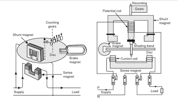
Induction-type Single-phase Energy Meter
An induction-type instrument can be used as an ammeter, voltmeter, or wattmeter, the induction-type energy meters are more popular. Induction-type single-phase energy meter is used invariably to measure the energy consumed in an AC circuit in a prescribed period where supply voltage and frequency are constant. The energy meter is an integrating instrument that measures the total quantity of electrical energy supplied to the circuit in a given period.
Principle
The basic principle of an induction-type energy meter is electromagnetic induction. When AC flows through two suitably located coils (current coil and potential coil), they produce the rotating magnetic field that is cut by the metallic disc suspended between the coils, and thus, an emf is induced in the disc that circulates eddy currents in it. By the interaction of rotating magnetic field and eddy currents, electromagnetic torque is developed that causes the disc to rotate. This is the same principle that is applied in single-phase induction motors.
A single-phase energy meter has four essential parts:
Operating system
Moving system
Braking system
Registering system
Operating System
The operating system consists of two electromagnets. The cores of these electromagnets are made of silicon steel laminations. The coils of one of these electromagnets (series magnet) are connected in series with the load and are called the current coil. The other electromagnet (shunt magnet) is wound with a coil that is connected across the supply, called the pressure coil. The pressure coil, thus, carries a current that is proportional to supply voltage.
Shading bands made of copper are provided on the central limb of the shunt magnet. Shading bands, as will be described later, are used to bring the flux produced by a shunt magnet exactly in quadrature with the applied voltage.
Moving System
The moving system consists of a light aluminum disc mounted on a spindle. The disc is placed in the space between the series and shunt magnets. The disc is so positioned that it intersects the flux produced by both the magnets. The deflecting torque on the disc is produced by an interaction between these fluxes and the eddy current they induce in the disc. In energy meters, there is no control spring as such, so there is the continuous rotation of the disc.
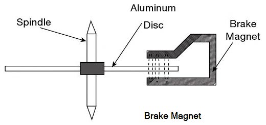
Braking System
The braking system in an induction type energy meter consists of a braking device which is usually a permanent magnet positioned near the edge of the aluminum disc. The arrangement is shown in Figure.
The emf induced in the aluminum disc due to relative motion between the rotating disc and the fixed permanent magnet (brake magnet) induces an eddy current in the disc.
When the disc rotates in the air gap, eddy currents are induced in the disc which opposes the cause producing them i.e. relative motion of the disc with respect to the magnet. This eddy current, while interacting with the brake magnet flux, produces a retarding or braking torque.
This braking torque is proportional to the speed of the rotating disc. When the braking torque becomes equal to the operating torque, the disc rotates at a steady speed.
The position of the permanent magnet with respect to the rotating disc is adjustable. Therefore, braking torque can be adjusted by shifting the permanent magnet to different radial positions with respect to the disc.
Registering System
The function of a registering or counting system is to continuously record a numerical value that is proportional to the number of revolutions made by the rotating system.
Ques.50. Which of the following can be used to measure frequency?
Anderson’s Bridge
De-Sauty’s Bridge
Owen’s Bridge
Wien’s Bridge✓
Wien’s Bridge
Wien’s bridge is primarily used for the determination of an unknown frequency. However, it can be used for various other applications including capacitance measurement, in harmonic distortion analyzers, where it is used as the notch filter. and also in audio and HF oscillators.
Wien’s bridge is frequency sensitive. Thus, unless the supply voltage is purely sinusoidal, achieving balance may be troublesome, since harmonics may disturb the balance condition. The use of filters with the null detector in such cases may solve the problem.


SIR PLEASE ADD MORE EXAMS QUESTION PAPERS ALSO,LIKE STATE JE ,AE AND PSU’S