Ques.41. Which one of the following is the dimension of energy?
ML2/T3
ML2/T2✓
T2/ML2
ML2/QT2
The dimension of energy is the same as that of work.
Finding the dimension of work:
Work = Force × Displacement
Force = Mass × Acceleration
Acceleration = Velocity/Time
Velocity = Distance/Time
Now we will start solving all the from the bottom i.e from the velocity
Displacement, Length = L & Time = T , Mass = M
⇒ Velocity = Displacement / Time
Velocity = [ M L T−1]
⇒ Acceleration = Velocity ⁄ Time = [ M0 L T−1] ⁄ [T]
Acceleration = [M0 L T−2]
⇒ Force = Mass × Acceleration = [M] × [M0 L T−2]
Force = [M L T−2]
⇒ Work = Force × Displacement = [M L T −2] × [L]
Work =[M L2 T −2] or [M L2 ⁄ T2]
Ques.42. Which one of the following statement is NOT TRUE about the MI type instruments?
MI type Instruments are suitable for both AC and DC circuits
Frictional error in MI type instruments is very less.
The torque weight ratio of MI type instruments is high
The instrument cost is much higher as compared to PMMC type instruments✓
Moving – Iron (M.l.) Ammeters and Voltmeters
This type of instrument is principally used for the measurement of alternating currents and voltages, though it can also be used for d.c. measurements. There are two types of moving-iron instruments.
(i)Attraction type in which a single soft-iron vane (or moving iron) is mounted on the spindle and is attracted towards the coil when operating current flows through it.
(ii) Repulsion type in which two soft-iron vanes are used; one fixed and attached to the stationary coil while the other is movable (i.e. moving iron) and mounted on the spindle of the instrument. When operating current flows through the coil, the two vanes are magnetized, developing similar polarity at the same ends. Consequently, repulsion takes place between the vanes and the movable vane causes the pointer to move over the scale.
Attraction Type Instrument
Construction
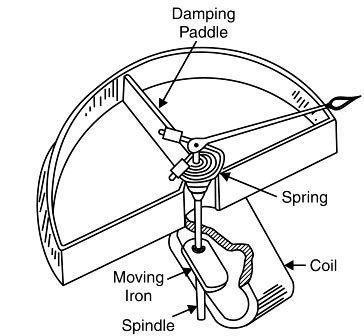
The sectional view of an attraction-type moving iron instrument is shown in Figures It consists of a stationary hollow cylindrical coil. An oval-shaped soft iron piece is mounted eccentrically to the spindle to which a pointer (needle) is attached. The controlling torque is provided by spring control method while damping torque is provided by air friction, as shown in Figures
Working of Attraction Type. When the instrument is connected to the circuit to measure current or voltage, the operating current flowing through the coil sets up a magnetic field. In other words, the coil behaves like a magnet and therefore it attracts the soft-iron piece towards it. The result is that the pointer attached to the moving system moves from zero position. The pointer will come to rest at a position where deflecting torque is equal to the controlling torque. If the current in the coil is reversed, the direction of the magnetic field also reverses and so does the magnetism produced in the soft-iron piece. Hence, the direction of the deflecting torque remains unchanged. For this reason, such instruments can be used for both d.c. and a.c. measurements.
Deflecting torque:- Torque in the attraction-type moving-iron instrument, the deflecting torque is due to the force of attraction between the field of the coil and the moving iron disc.
The magnetization of the iron disc or pole strength is proportional to the magnetic field strength H. The force F pulling the disc inwards is proportional to the Pole strength M of the disc and field strength H.
Therefore the deflecting torque
Td ∝ MH
M ∝ H
H ∝ I
Td ∝ I2
Hence the deflecting torque depends on the attraction between the field of the coil and the moving iron disc. That is, in an ammeter, the torque is roughly proportional to the current squared. The instrument, therefore, has the square-law response. The deflection is proportional to the mean value of the square of the current. When used on AC, it indicates the RMS or effective value of current (or voltage).
Controlling Torque:- In this type of instrument, controlling torque is obtained by either with a spring or by gravity. In Fig. a spring has been used for the controlling torque.
Damping Torque:- In this type of instrument, pneumatic type damping is used. Eddy currents cannot be employed because the presence of a permanent magnet, required for such a purpose, would affect the deflection and hence the reading of the instrument.
As the deflection torque, in both attraction and repulsion-type moving-iron instruments, is proportional to the square of the current, the scale is crowded (not uniform) at the beginning. It is more so with the gravity control as the controlling torque is proportional to the sine of the angle of deflection, i.e. sine θ. This is rectified to some extent by making the moving vanes of a suitable shape.
Advantages of Moving Iron Instrument
Moving iron instruments are the cheapest elements and are robustly used in industry.
Usable in both a.c. and d.c. circuits.
They are simple in construction
They possess high operating torque and can withstand overload momentarily.
Disadvantages of Moving Iron Instrument
Have a non-linear scale.
Cannot be calibrated with a high degree of precision for d.c. on account of the effect of hysteresis in the iron vanes.
Deflection of up to 240° only may be obtained with this instrument.
The instrument will always have to be put in the vertical position if it uses gravity control.
High power consumption and poor sensitivity
Change in frequency introduces errors and these cannot be calibrated with the high degree of Precision
Ques.43. Which one of the following statement is NOT TRUE about multimeter?
The multimeter can be used for the measurement of voltage
The multimeter can be used for the measurement of power✓
The Multimeter can be used for the measurement of current
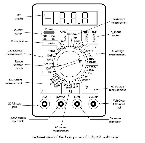
A multimeter, also known as a VOM (Volt-Ohm-Milliammeter) is a combination of a voltmeter, ohmmeter, and a current meter. it is an indicating electronic instrument that can be used for the measurement of three quantities, namely voltage, current, and resistance. This instrument can also be used for both dc and ac voltages and currents. Multimeters are available in both analog and digital form. Although analog multimeters are being replaced by digital multimeters.
Note:- Power can be measured by measuring the voltage and current in a circuit and finding the product of the two. A single meter that indicates power in the circuit is called a wattmeter.
Ques.44. Which one of the following is the main cause of magnetic decay in PMMC type instruments?
Variation in the resistance of the moving coil
Quality of spring
Aging of the spring
Aging of the magnets✓
Permanent Magnets Moving Coil “PMMC” Instrument
These instruments are used either as ammeters or voltmeters and are suitable for d.c. work only. This type of instrument is based on the principle that when a current-carrying conductor is placed in a magnetic field, the mechanical force acts on the conductor. The coil placed in the magnetic field and carrying the operating current is attached to the moving system. With the movement of the coil, the pointer moves over the scale to indicate the electrical quantity being measured. This type of movement is known as the D’Arsonval movement.
Errors In PMMC Instrument
The basic sources of errors in PMMC instruments are friction, temperature, and aging of various parts. To reduce the frictional errors ratio of torque to weight is made very high.
The most serious errors are produced by the heat generated or by changes in the temperature. This changes the resistance of the working coil, causing large errors. In the case of voltmeters, a large series resistance of a very low-temperature coefficient is used. This reduces the temperature errors.
The aging of permanent magnet and control springs also causes errors. The weakening of the magnet and springs cause opposite errors. The weakening of the magnet causes less deflection while the weakening of the control springs causes large deflection, for a particular value of current. The proper use of material and pre-aging during manufacturing can reduce tt errors demo the weakening of the control spring.
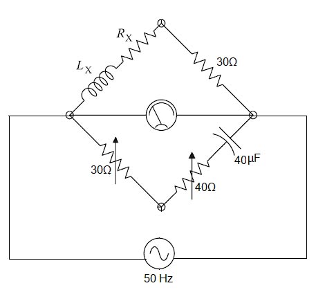
Ques.45. Determine the quality factor in Hay’s bridge given below, if the bridge is supplied by a frequency of 50 Hz.
2✓
1
0
4
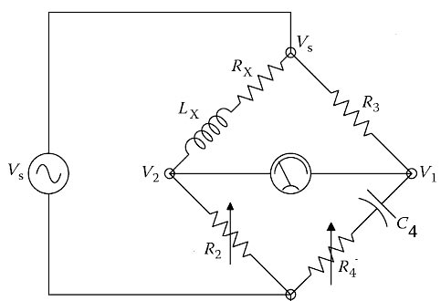
Hay’s bridge is a modification of Maxwell’s bridge. This method of measurement is particularly suited for high Q inductors.
The unknown inductor LX of effective resistance RX is compared with the standard known variable capacitor C4. This bridge uses a resistance R4 in series with the standard capacitor C4 (unlike in Maxwell’s bride where R4 was in parallel with C4). The other resistances R2 and R3 are known as no-inductive resistors.
The quality factor of the Hay bridges is given as
Q = ωLx ⁄ Rx = 1 ⁄ ωC4R4
where ω = 2πf = 2 × 3.14 × 50 = 314
Q = 1 ⁄ ωC4R4 = 1 ⁄ 314 × 40 × 10−6 × 40
Q = 2
Ques.46. Determine the apparent power (in W) of a circuit, if the circuit has a power factor of 0.8 and the reactive power of the circuit is 60 W
80
10✓
60
55
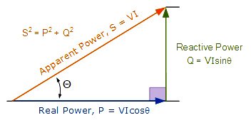
We can determine the relation between apparent power and reactive power by the power triangle
Reactive Power in an A.C circuit is given as
Q = V.I.Sinθ
or
V.I = Q/Sinθ———-(1)
Apparent power in an A.C circuit is
S = V.I
or
S = Q/Sinθ——-(From equation 1)
Power factor cosφ = 0.8
cosφ = 0.8
Sin2φ = 1 − cos2φ
Sin2φ = 1 − (0.8)2
Sinφ = 0.6
S = 60/0.6
S = 10 watt
Ques.47. A building has 3 floors and each floor has 4 fans of 50 W that operates for 12 hours a day and one air conditioner of 3000 W that operates for 2 hours per day in the month of the June. Determine the energy consumption (in kWh) of the building in June.
512
252
396✓
504
Energy consumption or power consumption refers to the electrical energy per unit time is given as
Energy consumption = Power × Time
(i) Since the building has 3 floors and each floor has 4 fans of 50 W that operates for 12 hours
3 × 4 × 50 × 12 × 30 = 216000 Watt.hr
One air conditioner working for 2 hours per day
1 × 3000 × 2 × 30 = 180000 Watt.hr
Total energy consumption
216000 + 180000 = 396000 watt-hr
= 396 kWh
Ques. 48. Determine the reading (in kW) of both the wattmeters used to measure the power of a three-phase three-wire system having an input of 6 kW and power factor of 1
4, 2
5, 1
3, 3✓
6, 0
The reading of two wattmeters can be expressed as
W1 = VLILcos(30 + φ) W2 = VLILcos(30 − φ)
(i) When PF is unity ( φ = 0°)
W1 = VLILcos30° W2 = VLILcos30°
Both wattmeters read equal and positive reading i.e upscale reading
Total Power = W1 + W2
And
W1 = W2
Total Power = 6 kW
∴ W1 = 3kW
&
W2 = 3kW
Ques.49. What will be the secondary voltage (in V) of a potential transformer, if the value of system voltage is 11,000 V, the turn’s ratio of the potential transformer is 108 and the percentage voltage error of the transformer is 5%?
86.8
93.6
84.6
96.8✓
System voltage i.e Nominal voltage = 11000 V
Transformation ratio of the potential transformer is
V1/V2 = N1/N2
V1/V2 = 108
Primary voltage = Turn ratio × Secondary voltage = V2 × 104 = 108V2
Percentage of error is the Potential error
= (Nominal voltage − Primary voltage)/Primary voltage
5% = (11000 − 108V2)/108V2
1/20 = (11000 − 108V2)/108V2
108V2 = 220000 − 2160V2
2268V2 = 220000
V2 = 97 V
Ques.50. Determine the full-scale reading (in kV) of a PMMC type voltmeter, when the internal resistance of the voltmeter is 230 kilo-ohms, the series resistance connected with the voltmeter is 70 kilo-ohms and the sensitivity of the voltmeter is 3 kilo-ohms/volt
200
150
100✓
250
The sensitivity of a voltmeter is given in ohms per volt. It is determined by dividing the sum of the Internal resistance of the meter (Rm) plus the series resistance (Rs), by the full-scale reading in volts. In equation form, sensitivity is expressed as follows:


sir don’t tick the answers. please mention them in explanations only.
thanku for your feedback Akshat..We will change this format soon