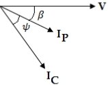
Ques 11. Phasor diagram of load voltage (V), current in pressure coil (I P ) and current in the current coil (I C) is shown in the figure when an electrodynamic wattmeter is used to measure power. The reading of the wattmeter will be proportional to
cos(β + ψ)
cosψ
cosβcosψ
cosβcos(β + ψ)
Answer 3. cosβcosψ
Explanation:
P = VI cos β. Ic cos ψ
Where β is the angle by which Ip is lagging behind applied voltage V
ψ is the power factor of the load
Therefore the reading of the wattmeter will be proportional to
P ∝ cos β cos ψ
Ques 12. Two parallel conductors carrying current in opposite directions will exert on each other
An attractive force
A repulsive force
An axial force
No force
Answer.2. A repulsive force
Explanation:
If the current flowing in the same direction then the conductor attracts each other and if the current flowing in the opposite direction then the conductor generates a repulsive force.
Ques 13. The unit of the reluctance of the magnetic circuit is
AT/m
Weber/m
AT/Weber
Weber/AT
Answer.3. AT/Weber
Explanation:
Reluctance is defined as
ℜ = F/Φ
F = magnetomotive force (MMF) in ampere-turns
Φ = the magnetic flux in webers.
Therefore the unit of Reluctance is ampere-turns per Weber ( AT/Weber) (a unit that is equivalent to turns per Henry)
Ques 14. In indicating instrument the springs are mainly used to
Conduct the current on the coil
Hold the pivot in position
Control the pointer movement
Reduce the vibration of the pointer
Answer.3. Control the pointer movement
Explanation:
Spring provides the controlling force in the measuring instrument if the controlling force is absent the pointer will not comes back to starting position i.e zero when the current is removed.
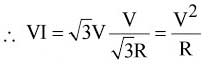
Ques 15. A balanced 3-phase, 3-wire supply feeds balanced star-connected resistors. If one of the resistors is disconnected, then the percentage reduction in load will be
33.33 %
50 %
66.67 %
75 %
Answer.2. 50
Explanation:
Underbalanced condition P = √3
If one of the resistors is disconnected it becomes a single-phase circuit with power
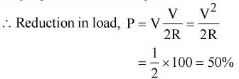
Ques 16. The total flux at the end of a long permanent bar magnet is 100×10 -6 Wb.The end of its magnet is withdrawn through a 1000 turn coil in 1/20 seconds. The induced emf in the coil is
20.0 V
2.0 V
0.2 V
0.02 V
Answer.2. 2.0 V
Explanation:
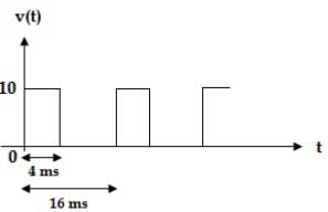
Ques 17. In reference to the figure, the voltage waveform v(t) is measured by a PMMC, a PMMC combined with the bridge rectifier, and a moving iron (MI) instrument. Two lists are provided thereafter
The correct option relating to the instrument and their reading is
a-i, b-ii, c-iii
a-iii, b-ii, c-i
a-ii, b-iii, c-i
a-iii, b-i, c-ii
Answer.2. a-iii, b-ii, c-i
Explanation:
PMMC type instrument measure average value
= Area of graph / Total Time
= Area of Graph = 10 x 4 = 40 unit
= Total time = 16 ms
= 40 /16 = 2.5 V
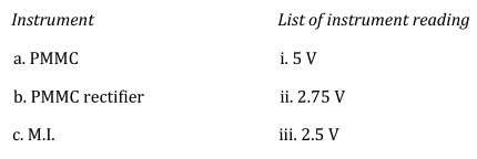
Ques 18. The switching transistor as shown carries on the collector side an RMS current of 8 mA. If the frequency of rectangular pulse train v i is 50 Hz, then the on-time of the transistor is
20 ms
6.4 ms
12.8 ms
16 ms
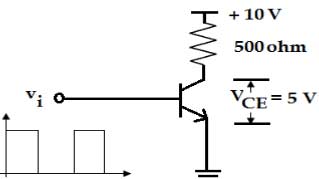
Ques 19. An ammeter of resistance Rm is placed in an arrangement as shown in the figure. The material of Rm, Rsh is copper whereas that of Rs, Rx is manganin. The condition for which the meter performance is compensated against the temperature is
1/Rm + 1/Rsh = 1/Rs + 1/Rx
RmRsh = RsRx
Rm + Rsh = RsRx
Rm/Rs =Rsh/Rx
[box type=”info”] Answer 4. Rm/Rs =Rsh/Rx
Explanation:
The condition for which the meter performance is compensated against the temperature will be when the resistance material is equally balanced
RmRx= RshRx
Rm/Rs =Rsh/Rx
Ques 20. If a 110 V, 50 Hz is supplied across a PMMC voltmeter of full-scale range 0-220 V and internal resistance of 10 kΩ, the reading of the voltmeter will be
0 V
110 √2 V
78 V
55 V
Answer 1. 0V
For sinusoidal voltage, PMMC reads zero
PMMC type instrument uses two permanent magnets in order to create the stationary magnetic field. If we apply AC current to these types of instruments the direction of current will be reversed during the negative half cycle and hence the direction of torque will also be reversed which gives the average value of torque zero.
Also If a.c. supply given to these instruments, an alternating torque will be developed. Due to the moment of inertia of the moving system, the pointer will not follow the rapidly changing, alternating torque and will fail to show an,y readings


Hi admin,
Can you pls mail me the ssc JE previous year paper with solution by mail ([email protected])
Will be highly thankful for the favour.
SSC JE electrical previous years paper with solution
Check your mail @Sumit Abrol
Hi admin,
Waiting for the previous years JE electrical paper PDF mail pls support .
Sorry for the delay Sumit check your mail box now
Thanks for the support
Ok i will give you the pdf by tommorow @Sumit Abrol
Nice collection sir .plz send me all paper in pdf
Sir,
Please deeply explain question number:-98.
Bro please provide questions number 98 with solutions