Ques 21. To maximize the driving torque in an induction type instrument, the flux produced by the shunt coil and series coil should be
In phase with each other
In quadrature with each other
Displaced by 45° with respect to each other
Out of phase with respect to each other
Answer.2. In quadrature with each other
Explanation:
The Deflecting torque of Induction type Instrument is given as:
Td = Φ1Φ2 sinβ cosα
where Φ = flux
β & α are the phasor angle
The torque in the Induction type instrument is directly proportional to the cosα. Therefore in order to maximize the torque, the angle “α” should be near zero.
The torque in the Induction type instrument is directly proportional to the sinβ. Therefore the angle β should be nearer to 90° in order to maximize the torque. The angle β is the angle between two shunt coil flux and series coil flux and quadrature means 90°.
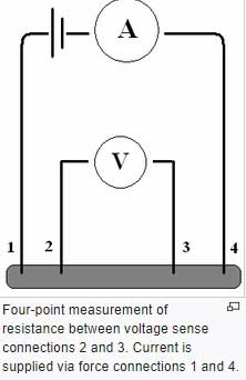
Four-terminal sensing is also known as Kelvin sensing, which measures very low resistances using four-terminal sensing. Each two-wire connection can be called a Kelvin connection.
When a Kelvin connection is used, the current is supplied via a pair of source connections (current leads). These generate a voltage drop across the impedance to be measured according to Ohm’s law V=IR.
A pair of sense connections (voltage leads) are made immediately adjacent to the target impedance so that they do not include the voltage drop in the force leads or contacts.
Since almost no current flows to the measuring instrument, the voltage drop in the sense leads is negligible hence accurate measurement can be obtained.
It is usual to arrange the sense wires as the inside pair, while the force wires are the outside pair.
Ques 23. Examine the two statements ‘A’ and ‘R’ and select your answer.
Statement A: Switching off a lamp in the house produces noise in a radio.
Statement R: The switching operation produces an arc across separating contacts.
Both A and R are true and R is a correct explanation of A
Both A and R are true and R is not a correct explanation of A
Both A and R are true and R is not a correct explanation of A
A is false but R is true
Answer.1. Both A and R are true and R is a correct explanation of A
Explanation:
Statement A:
Usually, a radio will make a sharp ‘pop’ when another electrical item is switched off.
The cause of the noise is the arc that momentarily bridges the contacts of the lamp’s switch when it is opened (shut off).
The arc produces radio-frequency energy, which nearby radios (especially AM, but sometimes also FM) detect.
Since the radio can’t differentiate between intended and unintended signals, it will reproduce whatever comes its way
Statement R:
During the opening of the contact, the medium between the contacts gets highly ionized therefore low resistive path is created between the contacts and the current tends to flow through that path.
Hence both the statement are true and A is the correct explanation of Statement R.
Ques 24. The small pockets of air in the high voltage cable provided ____________ relative permittivity, ____________ electric field at these sites breakdown is likely to be initiated.
High, High
Low, Low
Low, High
High, Low
Answer.3. Low, High
Explanation:
The relative permittivity of air is low( i.e about 1.0006) than the insulation material, therefore, they have a higher voltage gradient then the surrounding insulation.
The electric discharge is high enough to ionize the air and cause the corona discharge.
Ques 25. The capacitance measured between any two cores of a 3-core cable with the sheath earthed is 3 μF. The capacitance per phase will be
1.5 μF
6 μF
1 μF
None of the above
Answer 2. 6μF
The capacitance to neutral is twice the capacitance between conductors, that is,
CN=2CAB = 2 x 3 = 6μF
Ques 26. In an insulated cable having core diameter d and overall diameter D, the ratio of maximum to minimum dielectric stress is given by
(D/d) 1/2
(D/d) 2
D/d
d/D
Answer.3. D/d
Explanation:
The ratio of minimum and maximum stress in the insulation of the single-core cable is
gmax / gmin = D / d
Where D = Sheath Diameter and d = Core Diameter
Note: The expression of the same will be explained in the theoretical section
Ques 27. Compared to the breaking capacity of a circuit breaker, its making capacity should be
More
Less
Equal
The two are unrelated to each other
Answer.1. More
Explanation:
Making capacity used the peak value of current while breaking capacity work on the RMS value of current that’s why making capacity is more than breaking capacity. Let’s explain in detail.
Breaking capacity of Circuit Breaker
When the breaker is closed and a fault occurs then it closes in the transient state(in the transient state DC offset become zero) so the current capacity at this instant is only the RMS value of current(symmetrical component)in the transient state which is also called breaking capacity of the breaker.i.e
Breaking capacity=rms value of breaking current in the transient state.
Making Capacity Of Circuit Breaker
Now when the breaker is going to be closed and at that time fault occurs then it will close the sub-transient state and the current-carrying capacity at this instant contains the RMS value of current (the symmetrical component in the transient state) and the DC offset current in the sub-transient state which is also called Making capacity of the breaker at the sub-transient period amount of arc produce will be very high. Thus making capacity is very high. i.e
Making Capacity=DC offset current+rms value of breaking current in a transient state
Thus Making capacity > Breaking Capacity
Ques 28. In electronic circuits, for blocking the DC component of a voltage signal, a/an ____________ is connected in series with the voltage source.
Capacitor
Diode
Resistor
Inductor
Answer.1. Capacitor
Explanation:
Why does a capacitor block DC but pass AC?
A capacitor is nothing but 2 metal plates separated by an insulator. The insulator can be anything like paper, air, rubber, etc.
When a capacitor is connected to a voltage source, positive charges from the positive terminal of the voltage source and negative charges(electrons) from the negative terminal of the voltage source, travel and GET ACCOMMODATED ON BOTH THE PLATES OF THE CAPACITOR.
Once the capacitor gets fully charged it will now act as the insulator and it doesn’t allow current to pass through it.
Now as we know that the voltage value of DC remains constant for all the time the power supply is ON. Hence capacitor gets charged to its total limit and thus doesn’t allow any current to flow hence DC BLOCKED.
Talking about AC it is the time-varying Voltage i.e the polarity of AC changes from time T1 to T2, therefore, at time T1, the capacitor gets charged such that the positive charges are accommodated on the left plate.
After time T1, the polarity changes (because the voltage source is AC), and now at the start of T2, voltage source V will attract the negative and positive charges from the respective plates to its terminals, and the current will flow in another direction. And because the capacitor is losing its charges hence the Capacitor is getting discharged.
Ques 29. For n-type semiconductors, the doping material is
Tetravalent
Pentavalent
Trivalent
Bivalent
Answer.2. Pentavalent
Explanation:
An N-Type semiconductor is created by adding pentavalent impurities like phosphorus (P), arsenic (As), or antimony (Sb), bismuth.
A pentavalent impurity is called a donor because it is ready to give a free electron to a semiconductor. The impurities are called dopants.
The purpose of doing this is to make more charge carriers, or electrons available in the material for conduction.
In n-type semiconductors the number of electrons is more than the holes, so electrons are measured as majority charge carriers and holes are referred to as minority charge carriers.
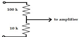
Ques 30. An attenuator probe as shown is connected to an amplifier of input capacitance 0.1 μF. The value of C that must be connected across 100 kΩ to make the overall gain independent of frequency, is


Hi admin,
Can you pls mail me the ssc JE previous year paper with solution by mail ([email protected])
Will be highly thankful for the favour.
SSC JE electrical previous years paper with solution
Check your mail @Sumit Abrol
Hi admin,
Waiting for the previous years JE electrical paper PDF mail pls support .
Sorry for the delay Sumit check your mail box now
Thanks for the support
Ok i will give you the pdf by tommorow @Sumit Abrol
Nice collection sir .plz send me all paper in pdf
Sir,
Please deeply explain question number:-98.
Bro please provide questions number 98 with solutions