SSC JE 2013 electrical question paper with solution | MES Electrical
Ques 1. The voltage wave v = Vm sin(ωt − 15°) volt is applied across an ac circuit. If the current leads the voltage by 10° and the maximum value of current is Im, then the equation of current is
I = Im sin(ωt + 5°) amps
I = Im sin(ωt – 25°) amps
I = Im sin(ωt + 25°) amps
I = Im sin(ωt – 5°) amps
Answer.4. I =Im sin(ωt – 5°) amps
Explanation:
From the above question, it is clear that the given circuit is capacitive in nature, therefore, the current is leading the voltage by 10°. Hence,
I = Im sin(ωt − 15° + 10°)
= I = Im sin(ωt – 5°) amps
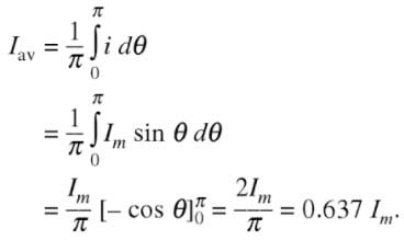
Ques 2. The average value of current (Iav) of a sinusoidal wave of the peak value (Im) is
Iav = Im/2
Iav = Im x Π/2
Iav = Im x 2/Π
Iav = Im/√2
Answer 3. Iav = = Im x 2/Π
Explanation:
Average Value Of Alternating Current
The average value is the DC value that produces the same charge as it is produced by an AC source in the given circuit for the given time.
Thus the average value of an alternating quantity = 0.637 x the maximum value of that alternating quantity.
NOTE: Average value for a sinusoidal wave cannot be calculated over a complete cycle as it is zero so it is calculated over half cycle from 0 to 180 degrees.
Ques 3. The emf induced in a coil is given by f = -N dΦ/dt, where ‘e’ is the induced emf, N is the number of turns and dΦ’ is the instantaneous flux linkage with the coil in time ‘dt’. The negative sign of the above expression is due to
Hans Christian Oersted
Andre-Marie Ampere
Michael Faraday
Emil Lenz
Answer.4. Emil Lenz
Explanation:
According to Lenz’s law, the induced EMF sets up a current in such a direction so as to oppose the very cause of producing it. Mathematically this expression is expressed in the negative sign
So, In Faraday’s law, the negative sign shows that the polarity of induced emf is such that it opposes any change in the magnetic flux of the coil.
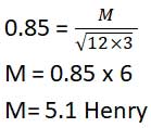
Ques 4. The mutual inductance between two coils having self-inductances 3 Henry and 12 Henry and coupling coefficient 0.85 is
12.75 Henry
5.1 Henry
0.425 Henry
1.7 Henry
Answer.2. 5.1 Henry
Explanation:
Coefficient of coupling or magnetic coupling coefficient is (K) is given as
Where L1 and L2 are self-inductance of coil 1 and 2 respectively
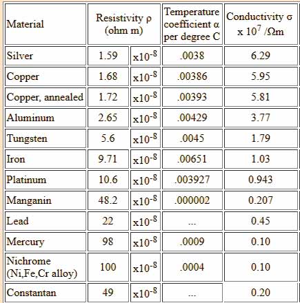
Ques 5. The temperature coefficient of resistance of copper at 20°c is
0.0045/°C
0.0017/°C
0.0393 /°C
0.0038/°C
Answer.3. 0.0393 /°C
Explanation:
Temperature Coefficient of Copper
The formula for temperature effects on resistance is
R = Rref [1 + α(T – Tref)]
Where
R = Conductor resistance at temperature T
Rref= Conductor resistance at reference temperature “Tref” usually 20°C
α = Temperature coefficient of the resistance of the conducting material
T = Conductor temperature in degree
Tref = Reference temperature for α is specified
The temperature coefficient for some common materials are listed below (@ 20ºC):
Ques 6. The load characteristics of the dc shunt generator are determined by
The voltage drop in armature resistance
The voltage drop due to armature reaction, the voltage drop due to decreased field current, and voltage drop in armature resistance
The voltage drop due to armature reaction and voltage drop in an armature resistance
The voltage drop due to armature reaction, the voltage drop due to decreased field current and the voltage drop in armature resistance and field resistance.
Answer.2. The voltage drop due to armature reaction, the voltage drop due to decreased field current and voltage drop in armature resistance
Explanation:
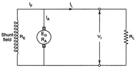
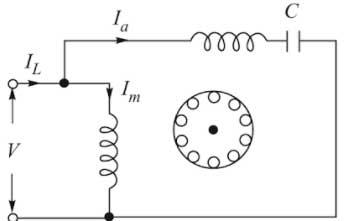
DC Shunt Generator
The above figure shows the circuit diagram of DC shunt generator where
IA = Armature current
IL = Load current
IF = Field current
RA = Armature Resistance
In the shunt generator, the field winding is connected parallel to the armature winding. When the load is connected across the armature, then there exists a voltage drop in field as well as armature winding. The voltage drop appears to IaRa armature reaction and weakened flux.
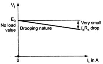
load characteristics of DC Shunt Generator
The load characteristics of DC shunt generator is also called as the external characteristics and It will only be slightly shifted from the internal characteristic as IL = Ia — If where If (field current) is usually very small.
Ques 7. How many watt-seconds are supplied by a motor developing 2 hp (British) for 5 hours?
2.68452×10 7 watt-seconds
4.476×10 5 watt-seconds
2.646×10 7 watt-seconds
6.3943×10 6 watt-seconds
Answer.1. 2.68452×10 7 watt-seconds
Explanation:
1 HP=745.7 Watt of Power
2 HP = 1491.4 Watt of Power
So, 2 HP motor working for 5 hours = 1491.4 x 5= 7457 Watt-hour
To convert Watt-Hour into Watt-sec multiply it by 3600
7457 x 3600 = 26845200
= 2.68452×10 7 watt-seconds
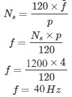
Ques 8. A 4-pole generator is running at 1200 rpm the frequency and time period of E.M.F generated in its coils are respectively.
50 Hz & 0.02 sec
40 Hz & 0.025 sec
300 Hz & 0.0033 sec
2400 Hz & 0.0260 sec
Answer.2. 40 Hz & 0.025 sec
Explanation:
f = 1/ t
t = 1 /40
= 0.025 sec
Ques 9. The single-phase Induction Motor(IM) which does not have a centrifugal switch is
Capacitor starts single phase IM
Resistance split single phase IM
Capacitor start capacitor run single phase IM
Permanent capacitor run single phase IM
Answer.4. Permanent capacitor run single phase IM
Explanation:
Permanent capacitor run single phase IM
Permanent capacitor single phase IM
In a permanent capacitor run, single phase Induction motor a single capacitor is connected in series with the auxiliary winding permanently thus the winding and the capacitor remains energized for both starting and running purpose.
Therefore permanent capacitor motor behaves virtually like the two-phase motor which is running on a single-phase supply.
The starting torque of this motor is very low as compared to the capacitor start motor and capacitor start run motor.
Since the same capacitor is used for the starting and running purpose, therefore, it is called a Permanent capacitor run single phase IM
Ques 10. When a multiplier is added to an existing voltmeter for extending its range, then its electromagnetic damping
Remains unaffected
Increases
Decreases
Changes in an amount depending on the controlling torque
Answer.3. Decreases
Explanation:
Electromagnetic Damping :
The movement of the coil in a magnetic field produces the eddy current in the metal former which further generates another magnetic field and interacts with the original magnetic field. Hence it produces a torque that opposes the motion of conducting coil and plate. Thus the magnitude of the current and the damping torque is dependent on the resistance of the circuit.
Voltage Multiplier
Multipliers are non-inductive high resistances connected in series with the voltmeter for the purpose of increasing the range of the voltmeter.
The resistance of the Multiplier greatly exceeds the meter’s internal resistance hence it reduces the electromagnetic damping action on the meter movement. The electromagnetic damping can be improved by shunting the meter with a capacitor, but this method increases the meter’s settling time.
24 thoughts on “SSC JE 2013 electrical question paper with solution”
Himanshu
Q.30 solution please
admin
I will mail you the solution Himanshu
sweeti saini
Ques 58. We have three resistances each of value 1 Ω, 2 Ω and 3 Ω. If all the resistances are to be connected in a circuit, how many different values of equivalent resistance are possible?
Five
Six
Seven
Eight
sir this question can be answered by if 3 resistances then the possible combinations 2^3=8.
if 4 resistances then the possible combinations 2^4=16.
just like in digital. this method applicable or not?
admin
Actually, the number of combination depends upon the value of resistor If all three resistors are of same value then the number of combination is 4.
I was also thinking the same way, researched so many books but didn’t find any appropriate formula for this. I am trying to find the method for this but If you have any information please share with us
sweeti saini
ok sir thank you very much
Rupa kumari
Thank you so much sir
It really helpful.
Can you please send me the solution of 2009 question paper [email protected]
admin
Ok Rupa I will upload the paper by tomorrow
Rupa kumari
Thank you sir
swapnil
nice work admin. I would like to appreciate your work for electrical boys.
admin
Thanks @swapnil
Dipti
No 30 ans please
admin
For compensated attenuator
C1R1 = C2R2
Put the value you will get your answer
Dipti
Thank you
Please explain no 97
admin
Dipti I will explain you the question tomorrow morning currently i am uploading the solution of SSC JE 2009. Sorry for the delay


Q.30 solution please
I will mail you the solution Himanshu
Ques 58. We have three resistances each of value 1 Ω, 2 Ω and 3 Ω. If all the resistances are to be connected in a circuit, how many different values of equivalent resistance are possible?
Five
Six
Seven
Eight
sir this question can be answered by if 3 resistances then the possible combinations 2^3=8.
if 4 resistances then the possible combinations 2^4=16.
just like in digital. this method applicable or not?
Actually, the number of combination depends upon the value of resistor If all three resistors are of same value then the number of combination is 4.
I was also thinking the same way, researched so many books but didn’t find any appropriate formula for this. I am trying to find the method for this but If you have any information please share with us
ok sir thank you very much
Thank you so much sir
It really helpful.
Can you please send me the solution of 2009 question paper
[email protected]
Ok Rupa I will upload the paper by tomorrow
Thank you sir
nice work admin. I would like to appreciate your work for electrical boys.
Thanks @swapnil
No 30 ans please
For compensated attenuator
C1R1 = C2R2
Put the value you will get your answer
Thank you
Please explain no 97
Dipti I will explain you the question tomorrow morning currently i am uploading the solution of SSC JE 2009. Sorry for the delay