Ques.41. Keeping the excitation constant, if the steam supply of an alternator running in parallel with another identical alternator is increased then
It would overrun the other motor
It will supply a greater portion of the load
Its power factor will decrease
Its power factor will increase
Answer.2. It will supply a greater portion of the load
Explanation
If the steam supply of one of the alternators is increased then its power input to the prime mover will also increase.
As we know that for parallel operation the speed must be the same for both the alternators, therefore the alternator with greater steam cannot overrun the alternator having the lesser steam supply.
The alternator with more steam supply utilizes its increased power to carry more load by advancing its angular position.
Ques.42. The zero power factor method is used to find
Voltage Regulation
Efficiency
Armature resistance
Synchronous Impedance
Answer.1. Voltage Regulation
Explanation
Zero power factor means that the load connected is either purely capacitive (zero leading) or purely reactive (zero lagging), therefore, there’s no KWatt (real power) consumed by the load.
As we know, the armature MMF depends on the armature current (Ia). when the load is purely resistive, the armature MMF is 90° Electrical behind the field MMF.
When the load is purely capacitive (zero leading pf), (Ia) advances by 90°, thus armature MMF is in phase with the field MMF and in this case, it helps in increasing the resultant MMF.
When the load is purely reactive ( zero lagging pf), Ia lags behind by 90° thus the voltage leads the current by 90°.
NOTE: The power factor being zero means the angle between the voltage and current phasors in 90 degrees. The term lagging implies that voltage leads to current. Cosine 90 is Zero and hence called Zero Power Factor load.
Ques.43. The load sharing between two steam-driven alternators operating in parallel may be adjusted by varying the
Power factor
Speed of the alternator
Steam supply to the prime mover
Frequency
Answer.3. Steam supply to the prime mover
Explanation
Zero power factor means that the load connected is either purely capacitive (zero leading) or purely reactive (zero lagging), therefore, there’s no KWatt (real power) consumed by the load.
As we know, the armature MMF depends on the armature current (Ia). when the load is purely resistive, the armature MMF is 90° Electrical behind the field MMF.
When the load is purely capacitive (zero leading pf), (Ia) advances by 90°, thus armature MMF is in phase with the field MMF and in this case, it helps in increasing the resultant MMF.
When the load is purely reactive ( zero lagging pf), Ia lags behind by 90° thus the voltage leads the current by 90°.
NOTE: The power factor being zero means the angle between the voltage and current phasors in 90 degrees. The term lagging implies that voltage leads to current. Cosine 90 is Zero and hence called Zero Power Factor load.
Ques.44. The active power of an alternator can be varied by
Increasing field excitation
Changing prime mover speed
Decreasing field excitation
Decreasing Frequency
Answer.2. Changing prime mover speed
Explanation
The alternator rotor has to maintain a constant speed as it is designed to produce a certain voltage at the desired frequency.
However, the real power demand is variable and at any instant, it is the duty of the generator to match (supply) this real power demand.
When an alternator is connected to the grid if the electrical load increases that mean real power increases. This increase in real power takes place by rotor deceleration for a short duration of time.
The loading on the generator should not exceed the generator rating as it may lead to the heating of the stator.
Ques.45. Negative voltage regulation can be expected in the case of
High-speed alternator
Slow speed alternator
Leading power factor load
Lagging power factor load
Answer.3. Leading power factor load
Explanation
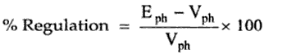
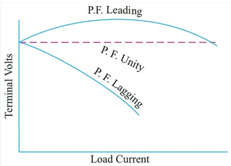
The voltage regulation of an alternator is defined as the change in its terminal voltage when the full load is removed, keeping field excitation and speed constant, to the rated terminal voltage.
Where Vph = Rated terminal voltage
Eph =No load-induced e.m.f
The value of regulation depends upon the load current and power factor of the load.
For lagging and unity power factors there is always a drop in the terminal voltage hence regulation values are always positive.
For leading or capacitive load the terminal voltage increase as the load current increase because armature flux is added up with the main field flux hence regulation is negative.
Ques.46. The main function of the pilot exciter in the larger alternator is
Driving dc auxiliaries
Battery charging
The exciting field winding of the main alternator
The exciting field winding of the main exciter
Answer.4. The exciting field winding of the main exciter
Explanation
An exciter is a device or combination of devices that supply the magnetizing current to generate the working flux.
In industrial applications basically, 3 types of exciters are used for an alternator.
Static exciter
Permanent magnet/Brushless Exciter
DC/Pilot exciter
To maintain the stability of the overall system the synchronous generator should respond quickly for sudden changes in the load and in order to attend these two dc generators are used, one as the main exciter and the other as a pilot exciter.
A pilot exciter is used to make the excitation of the generator independent of an external power source.
A pilot exciter is mounted on the rotor shaft and it excites the field coil of a separately excited dc generator called “ the main exciter.
Ques.47. The advantages of the parallel operation of an alternator are
Continuity of the supply
Proper load Sharing
Increase in the efficiency
All options are correct
Answer.4. All option are correct
Explanation
The advantages of the parallel operation of an alternator are
Proper load sharing
Increase in reliability
Increase in efficiency
Reduce losses
Easy to operate
Cheaper (reduce capital cost)
Continuity of supply
Continuity of the supply
If the single large unit is disabled for maintenance purposes then the station will be no longer functional; Whereas if one of the several smaller units is in need of repair, the other smaller units are still available to maintain continuity of the supply.
Efficiency
During light load, one or more alternators may be shut off while a few operate at full load. This provides more efficiency.
Future Expansion & reduction in cost
An additional set of an alternator can be connected in parallel to meet the increasing demand thereby reducing the initial cost of setting up another unit.
Ques.48. In the synchronous machine, the generated V curve is drawn between
Field current on X-axis and armature current on Y-axis
Field current on Y-axis and armature current on X-axis
Field current on Y-axis and Power factor on X-axis
Field current on X-axis and Power factor on Y-axis
Answer.1. Field current on X-axis and armature current on Y-axis
Explanation
V curve is the graph showing the relation of armature current as a function of field current in synchronous machines.
In the case of a synchronous generator, the V curve is drawn between field current on the X-axis and armature current on the Y-axis.
The purpose of the curve is to show the variation in the magnitude of the armature current as the excitation voltage of the machine is varied.
Ques.49. In the synchronous generator, the Inverted V curve is drawn between
Field current on X-axis and armature current on Y-axis
Field current on Y-axis and armature current on X-axis
Field current on Y-axis and Power factor on X-axis
Field current on X-axis and Power factor on Y-axis
Answer.4. Field current on X-axis and Power factor on Y-axis
Explanation
The Inverted V Curve is a graph showing the relation of power factor as a function of field current.
In the case of a synchronous generator, the inverted V curve is drawn between field current on X-axis and Power factor on Y-axis.
Similar to V Curve, its purpose is to show variation in power factor as the field current of the machine is varied.
Ques.50. A 10 pole 25 Hz alternator is directly coupled to and is driven by 60 Hz synchronous motor then the number of poles in a synchronous motor is
24 poles
12 poles
6 poles
3 poles
Answer.1. 24 poles
Explanation
Number of poles of alternator Pa = 10
F = 25 Hz (alternator)
F = 60 Hz (motor)
Then the number of poles of motor Pm =?
Since the synchronous motor is directly coupled hence
The synchronous speed of an alternator = Synchronous speed of the motor


Thanks for your efforts. Nicely explained all questions.
nice question
good answers
very good