Ques 81. A 4-pole, 50 Hz, the synchronous generator has 48 slots in which a double layer winding is housed. Each coil has 10 turns and is short pitched by an angle of 36o to electrical. The fundamental flux per pole is 0.25 Wb. The line to line induced emf, for a three-phase star connection is approximately
800 V
1000 V
1400 V
1500 V
Answer.C.1400 V
Explanation:-
Given Data
The number of Poles P = 4 No of slots = 48 Flux φ = 0.25 Wb Number of turns = 10
$\begin{array}{l}{K_d} = \dfrac{{\sin (m\alpha /2)}}{{m\sin \alpha /2}}\\\\{\text{where alpha is slot angle = }}\dfrac{{{\text{180 electrical}}}}{{{\text{No of slots/pole}}}}\\{\rm{\alpha }} = \dfrac{{180 \times 4}}{{48}} = 15^\circ \\\\{\text{m = no of slots per pole per phase}}\\\\m = \dfrac{{48}}{{4 \times 3}} = 4\\\\\therefore {K_d} = \dfrac{{\sin (60^\circ /2)}}{{4\sin (15^\circ /2)}}\\\\{K_d} = 0.9576\end{array}$
∴ EMF per phase Eph of an alternator is
Eph = 4.44.Kp.Kd.φ.f.Tph
Eph = 4.44 × 0.951 × 0.9576 × 0.25 × 50 × 160
Eph = 808.68
Line to Line induced EMF
EL = √3EPH
EL = √3 × 808.68
EL = 1400.67 V
Ques 82. A 3-phase, the 4-pole alternator has 48 stator slots carrying a 3-phase distributed winding. Each coil of the winding is short chorded by one slot pitch.The winding factor (Kw) is
0.9494
0.8565
0.9147
0.6190
Answer A.0.9494
Explanation:-
Given Data
The number of Poles P = 4 No of slots = 48 Phase = 3
Distribution factor Kd is given as
$\begin{array}{l}{K_d} = \dfrac{{\sin (m\alpha /2)}}{{m\sin \alpha /2}}\\\\{\text{where alpha is slot angle = }}\dfrac{{{\text{180 electrical}}}}{{{\text{No of slots/pole}}}}\\{\rm{\alpha }} = \dfrac{{180 \times 4}}{{48}} = 15^\circ \\\\{\text{m = no of slots per pole per phase}}\\\\m = \dfrac{{48}}{{4 \times 3}} = 4\\\\\therefore {K_d} = \dfrac{{\sin (60^\circ /2)}}{{4\sin (15^\circ /2)}}\\\\{K_d} = 0.9576\end{array}$
Sometimes distribution factor (Kd) and pitch factor (Kp) of an alternator are combined into a single factor called winding factor (Kw). The winding factor is the product of Kd and Kp i.e.
Kw = Kp × Kd
Kw = 0.9576 × 0.9914
Kw = 0.9494
Ques 83. A 6 pole alternator with 36 slots carries a 3-phase distributed winding. Each coil is short-pitched by one slot. The winding factor is given by
Ques 85. A part of an alternator winding consists of 8 coils in series, each coil having an emf of 80V (RMS) induced in it. Coils are placed in successive slots and have an electrical phase displacement of 30°. Then the emf of right coils in series is.
250 V
260 V
265.7 V
270.2 V
Answer C.265.7 V
Explanation:-
Given
Phase displacement angle α = 30°
No of slots per pole per phase (n) = Number of coil = 8
Airthmetic sum of voltage = Total Number of coils x Given voltage
= 8 x 80 = 640 V
The EMF of right coils in series is
Vector sum of voltage = Distribution factor x Airthmetic sum of voltage
= 0.4182 × 640
= 267. 6 V
Ques 86. If a 3 phase, 25 kV, 50Hz Star connected synchronous generator runs at 1000 rpm. Then the number of poles and voltage per phase is _______ & ________ respectively.
6 Poles, 15080.8 V
12 Poles, 15008 V
6 Poles, 13334.5 V
6 Poles, 14433.7 V
Answer 4. 6 Poles, 14433.7 V
Explanation:-
Given data
Frequency f = 50 Hz Line voltage VL = 25 kV = 25 x 103 V Speed Ns = 1000 RPM
The synchronous speed of an alternator is given as
Ns = 120f/P
P = 120f/N
P = 120 x 50/1000
P = 6
In star connection Voltage per phase is given by
VPH = VL ⁄ √3
VPH = 25 x 103 ⁄ √3
VPH = 14433.7 V
Ques 87. A 3-phase Star connected synchronous generator is rated at 15 kVA, 400V, and 50 Hz. If rated load at 0.8 pf lagging is supplied where resistance is 0.5Ω and synchronous reactance is 10Ω. Then the voltage regulation of an alternator is.
0.253
0.568
0.144
0.869
Answer. C. 0.144
Explanation:-
Given Data,
Line voltage VL= 400 V Alternator Rating = 15 KVA = 15 x 103 VA Resistance Ra = 0.5 Ω Synchronous Reactance XL = 10 Ω
Full Load current IL = VA ⁄ √3 VL
IL = 15 x 103 ⁄ √3 x 400
IL = 21.6 A
For star connection Voltage per phase is given by
VPH = VL ⁄ √3
VPH = 400 ⁄ √3
VPH = 230.9 V
Generated voltage per phase of an alternator is given as
EPH = VPH + ILRa + ILXL
= 230 + 21.6 × 0.5 + 21.6 × 10
= 457.7 V
The voltage regulation of an alternator is defined as the change in its terminal voltage when the full load is removed, keeping field excitation and speed constant, divided by the rated terminal Voltage.
Soif Vph = Rated terminal voltage
Eph = No load induced e.m.f
Voltage Regulation = (Eph − Vph)/Vph
= (457.7 − 400) ⁄ 400
= 0.144
Ques 88. A 30 MVA, 15 kV alternator will have a per phase nominal impedance of ______
9 Ω
15 Ω
7.5 Ω
10.5 Ω
Answer. C.7.5 Ω
The Nominal impedance of a synchronous machine is also called as the base Impedance. The nominal impedance of an alternator is the ratio of the rated line-to-neutral voltage divided by the rated line current. The nominal impedance is used as a base of comparison for other impedances that the alternator possesses.
Zbase = Vbase ⁄ Ibase
Apparent Power (S) = V x I
Zbase = V2base ⁄ Sbase
∴ Nominal Impedance
Zbase = (15000)2 ⁄ 30 × 106
Zbase = 7.5Ω
Ques 89. For the same power rating, an alternator is ________ that of a d.c. generator.
Larger in size than
Smaller in size than
Of the same size as
None of the above
Answer. 3.Larger in size than
Explanation:-
The efficiency of alternator increase with the increase in size because losses to heat are reduced.
The coefficient of efficiency can be increased by designing the machine to have reduced losses windings (copper losses) and magnetic circuit (iron losses). By increasing the cross-section of conductors, the resistance of copper conductors is decreased which leads to reduced copper losses. By increasing the cross-section of the magnetic circuit, the magnetic induction decreases for the same flux. Consequently, the iron losses are smaller. On the other hand, this approach to reducing the current density and magnetic induction leads to an increased volume and mass of the machine.
The efficiency of an alternator automatically improves as the power rating increases. For example, if an alternator of 1 kVA has an efficiency of 50%, a larger but similar model having a capacity of 10 MVA will have an efficiency of about 90%.
Ques 90. Electrical fault between two windings of the same phase of a generator having double star winding can be detected by the following protection in the generator
Short circuit fault
Earth fault protection
Inter turn fault protection
Overvoltage protection
Answer.3.Inter turn Fault protection
Explanation:-
The Merz-Price protection system gives protection against phase to phase faults and earth faults. It does not give protection against inter-turn faults. The inter-turn fault is a short circuit between the turns of the same phase winding. Thus the current produced due to such fault is a local circuit current and it does not affect the currents entering and leaving the winding at the two ends, where C.T.s are located. Hence Merz-Price protection cannot give protection against inter-turn faults.
In a single turn generator, there is no question of inter-turn faults but in multiturn generators, the inter-turn fault protection is necessary. So such inter-turn protection is provided for multiturn generators such as hydroelectric generators. These generators have double winding armatures. This means each phase winding is divided into two halves, due to the very heavy currents which they have to carry. This splitting of the single-phase winding into two is advantageous in providing inter-turn fault protection to such hydroelectric generators.
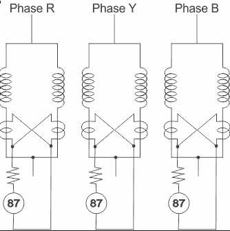
The scheme uses a cross differential principle. Each phase of the generator is doubly wound and split into two parts S1 and S2 as shown in Fig. The current transformers are connected in the two parallel paths of each phase winding.
The secondaries of the current transformers are cross-connected. The current transformers work on circulating the current principle. The relay is connected across the cross-connected secondaries of the current transformers.
Under normal operating conditions, when the two paths are sound then currents In the two parallel paths S1 and S2 are equal. Hence currents in the secondaries of the current transformers are also equal. The secondary current flows around the loop and Is the same at all the points. Hence no current flows through the relay and the relay inoperative.
If the short circuit is developed between the adjacent turns of the part Sit of the winding say then currents through S1 and S2 no longer remain the same. Thus unequal currents will be induced in the secondaries of the current transformers. The difference of these currents flows through the relay R. Relay then closes its contacts to trip the circuit breaker which isolates the generator from the system.
Such an inter-turn fault protection system is extremely sensitive but it can be applied to the generators having doubly wound armatures.


Thanks for your efforts. Nicely explained all questions.
nice question
good answers
very good