
Ques 11. The essential condition for parallel operation of two single-phase transformer is that they should have the same
- KVA Rating
- Turn Ratio
- Polarity
- All of the above
Answer 4. All of the above Explanation: Parallel operation of transformers There are a number of requirements that must be satisfied before two or more single-phase transformers can be ‘paralleled -i.e. before they can be connected in parallel with each other, in order to supply the same load. These requirements are Same voltage ratio:- If two single-phase transformers with different voltage ratios (or turns ratios) are connected in parallel across a common primary voltage, then their secondary voltages will obviously be different. Under ‘no-load’ conditions (i.e. with no load connected), this will result in a circulating current between the loop formed by the two secondary windings. As the impedance of a transformer’s windings is low, this circulating current can be quite high, resulting in unnecessarily high I2R losses. Similar percentage impedance:- A transformer’s percentage impedance can be determined by shortcircuiting the secondary winding with an ammeter, and gradually increasing the primary voltage until rated current flows in the secondary. The percentage impedance is then simply the ratio of that particular primary voltage to the rated primary voltage, expressed as a percentage. So, for example, if a particular transformer has a percentage impedance of, say, ‘5%’, then it would take just 5% of the rated primary voltage to cause 100% of the rated secondary current to flow through the short-circuited secondary winding. For unequal ratings, the numerical (ohmic) values of their impedances should be in inverse proportion to their ratings to have current in them in line with their ratings. A difference in the ratio of the reactance value to the resistance value of the per-unit impedance results in a different phase angle of the currents carried by the two paralleled transformers; one transformer will be working with a higher power factor and the other with a lower power factor than that of the combined output. Hence, the real power will not be proportionally shared by the transformers. Similar kVA rating:- Transformers with different kVA ratings will share the load more-or-less in proportion to those ratings (i.e. with each transformer carrying roughly its own share of the load), providing their voltage ratios are identical and their percentage impedances are close. However, it is generally recommended that the kVA-rating of any two transformers should never differ by more than a ratio of 2:1. Same Polarity:- The ‘polarity’ of a transformer describes the instantaneous direction of the potential difference induced across the secondary terminals of that transformer, relative to that across the primary terminals. The transformers should have the same polarity: The transformers should be properly connected with regard to their polarity. If they are connected within correct polarities then the two EMFs, induced in the secondary windings that are in parallel, will act together in the local secondary circuit and produce a dead short circuit.
Qus12. A transformer has negative voltage regulation when its load power factor is
- Lagging
- Leading
- Unity
- Any of the above
Answer.2. Leading Explanation: Voltage regulation is the change in secondary terminal voltage from no load to full load at a specific power factor of load and the change is expressed in percentage. E2 = no-load secondary voltage V2 = full load secondary voltage Voltage regulation for the transformer is given by the ratio of change in secondary terminal voltage from no load to full load to no load secondary voltage. Voltage regulation = $\frac{{{E_2} – {V_2}}}{{{E_2}}}$ It can also be expressed as, Regulation = $\frac{{{I_2}{R_{02}}\cos {\phi _2} \pm {I_2}{X_{02}}\sin {\phi _2}}}{{{E_2}}}$ Regulation depends on the leakage impedance of the transformer and on the power factor of the load.
Ques 13. The main purpose of performing short circuit test in a transformer is to measure its
- Copper loss
- Core loss
- Insulation Resistance
- Total loss
Answer.1. Copper Loss Explanation: Short circuit or Impedance test Short circuit test or Impedance test is performed to determine
⇒ Copper loss at full load
⇒ Equivalent impedance (Zo1 or Zo2)
⇒ Leakage reactance (Xo1 or Xo2)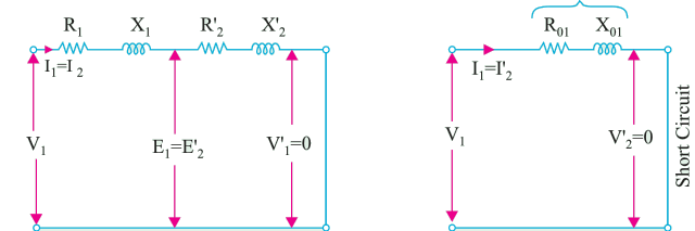
Ques 14. The short circuit test in a transformer is performed on
- Low voltage side
- High voltage side
- Either 1 & 2
- Both 1 & 2
Answer.2. High voltage side Explanation:
Therefore to get accurate results that test is done on the HV side.
Qus 15. Flash point of transformer insulating oil should be more than
- 100°
- >140°
- 75°
- Below 75°
Answer.2. >140° Explanation: Flash Point of Transformer Oil is defined as the temperature at which light hydrocarbon present in the transformer oil starts evaporating causing a flash on the introduction of the source under specified conditions.
Ques 16. Which of the following loss in a transformer is zero even at full load
- Eddy current loss
- Core loss
- Copper loss
- Friction loss
Answer.4. Friction loss Explanation: The transformer is a static device that is used to transfer electric power from one circuit to another without changing its frequency. The main function of a transformer is to raise as lower the voltage in a circuit with a corresponding decrease or increase in current at the same frequency. It works on the principle of Faraday’s law of Electromagnetic induction. Transformers have no moving parts, rugged and durable in construction. Since operation does not involve rotation of an armature, field system, or commutator, rotational, friction loss. and windage losses do not occur and its efficiency is thus high. For electrical ‘power’ purposes, i.e. transformers operating at 50 or 60 Hz, iron cores are essential and iron losses will occur. Winding copper losses are also present when current is supplied, nonetheless, the transformer is the most efficient of electrical machines and has a full-load efficiency of 95.5% for units of 5 kVA and 97.5% for units up to 1 MVA may be achieved.
Qus 17. In a transformer the resistance between its primary and secondary is
- Zero
- Infinite
- 1000 ohm
- 100 ohm
Answer.2. Infinite Explanation: In a transformer, the primary and secondary windings are not electrically connected therefore the resistance between them is ideally infinite but an autotransformer does the same using a single coil as primary with one or more tap for secondary in different parts of the coil. In this case, the resistance will ideally be zero or a short circuit.
Ques 18. The efficiency of two identical transformers under load conditions can be determined by
- Short Circuit test
- Open Circuit test
- No Load test
- Back to Back test (Sumpner Test)
Answer.4. Back to Back test (Sumpner Test) Explanation: To determine the maximum temperature rise of a transformer Sumpner’s test is performed. This test can also be performed to find out the efficiency of a transformer. With the help of Sumpner’s test both the open-circuit and short-circuit tests can be performed simultaneously. Efficiency at full load is η = (Full Load output)/(Full Load output + Core loss + copper loss) η = Wfull/(Wfull + W1 + W2)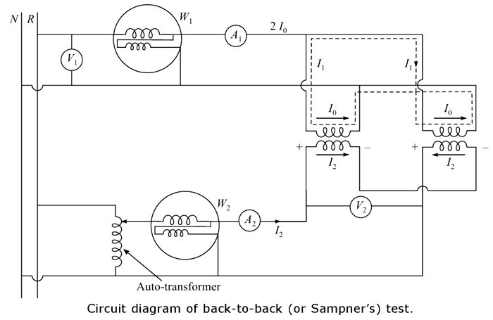
Qus 19. The transformer ratings are usually expressed in terms of
- KW
- KVAR
- KVA
- Volts
Answer.3. KVA Explanation: The rating of any electrical machine shows its ability to carry the mechanical load without showing any signs of overheating. There are two types of losses in a transformer ⇒ Iron Losses Therefore, the transformer rating is expressed as kVA and not as kW.
⇒ Copper loss
Ques 20. Which winding in a transformer has more number of turns?
- Secondary winding
- primary winding
- High voltage winding
- Low voltage winding
Answer.3. High Voltage Winding Explanation:

Thank you for providing MCQ is it useful for B.TECH ENTRANCE EXAM
Greatful
Power system Analysis and power system stability &design