
Ques.81. If in a synchronous motor, driving mechanical load and drawing current at lagging power from the constant voltage supply, its field excitation is increased, then its power factor
- Become More✓
- Become Less
- Remain constant
- All of these
A synchronous motor is a machine which converts a electric power into mechanical power at a constant speed called synchronous speed. It is a doubly excited machine because its rotor winding is excited by direct current and its stator winding is connected to an A.C supply. Stator: Stator is the stationary part of the machine. The three-phase armature winding is placed in the slots of the stator core and is wound for the same number of poles as the rotor. The stator is excited by a three phase ac supply as shown in the Figure Rotor: The rotor of synchronous motor can be of the salient pole or cylindrical pole (Non-salient) type construction. Practically most of the synchronous motor use salient i.e., projected pole type construction, except for exceedingly high-speed machines. The field winding is placed on the rotor and it is excited by a separate dc supply. Although the synchronous motor starts as an induction motor. it does not operate as one. After the armature winding has been used to accelerate the rotor to about 95% of the speed of the rotating magnetic field, direct current is connected to the rotor and the electromagnets lock in step with the rotating field. Notice that the synchronous motor does not depend on the induced voltage from the stator field to produce a magnetic field in the rotor. The magnet field of the rotor is produced by external DC applied to the rotor. This is the reason that the synchronous motor has the ability to operate at the speed of the rotating magnetic field. As the load is added to the motor, the magnetic field of the rotor remains locked with the rotating magnetic field and the rotor continues to run at the same speed. It should be noted that the changes in the dc field excitation do not affect the motor speed. However, such changes do alter the power factor of a synchronous motor. If all of the resistance of the rheostat is inserted in the field circuit, the field current drops below its normal value. A poor lagging power factor results. If the dc field is weak, the three-phase ac circuit to the stator supplies a magnetizing current to strengthen the field or the lagging reactive power will be drawn from A.C source to aid magnetization. This magnetizing component lags the voltage by 90 electrical degrees. The magnetizing current becomes a large part of the total current input. This gives rise to a low lagging power factor. If a weak dc field is strengthened, the three-phase ac circuit to the stator supplies less magnetizing current and the leading current is drawn from the ac source to compensate (oppose) the magnetization. Because this current component becomes a smaller part of the total current input to the stator winding, the power factor increases. The field strength can be increased until the power factor is unity or 100%. When the power factor reaches unity, the three-phase ac circuit supplies energy current only. The dc field circuit supplies all of the current required to magnetize the motor. The amount of dc field excitation required to obtain a unity power factor is called normal field excitation. The magnetic field of the rotor can be strengthened still more by increasing the dc field current above the normal excitation value. The power factor in this case decreases. The circuit feeding the stator winding delivers a demagnetizing component of current. This current opposes the rotor field and weakens it until it returns to the normal magnetic strength. Hence Higher PF means the low requirement of MMF for energy transfer, hence low magnetizing current requirement. The synchronous machine has separate DC excitation which reduces machine’s excitation dependency on main supply, hence better PF. whereas Induction motor has no such provisions, hence low Power factor.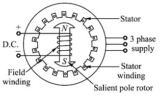
Ques.82. Electric charge measured in coulombs has the charge of how many electrons?
- 6.242 × 10¹⁸✓
- 6.242 × 10⁸
- 8.242 × 10¹⁸
- 8.242 × 10⁸
Electric charge is the physical property of matter that causes it to experience a force when placed in an electromagnetic field. The charge possed by the proton is equal to 1.602 × 10⁻¹⁹ whereas the charged possed by the electron is equal to -1.602 × 10⁻¹⁹. The symbol Q often denotes charge and the SI unit of electric charge is the coulomb (C). One coulomb is the fundamental SI unit of charge. It is defined as the charge in one Ampere of current passed for one second. So for making a charge of 1 Coulomb, the number of electrons required will be: Q = n × e Q = 1 C and e = 1.602 × 10⁻¹⁹. n = 1/(1.602 × 10-19) n = 6.24 x 10¹⁸ number of electrons
Ques.83. A protective device, which reduces the steepness of wavefront of a surge by absorbing surge energy is called
- Surge Diverters
- Surge absorber✓
- Switching surges
- Earthing screen
Surge Absorber The steepness of wavefront of travailing waves can cause damage to the apparatus in addition to the magnitude of the wave. More steeper is the traveling wave, the damage to the apparatus is more. Thus to reduce the steepness of wavefront of the surge, surge absorber is used. The surge absorber is a protective device which can reduce the steepness of wavefront of a surge and absorbs energy contained in travailing wave. Though the surge diverter and surge absorber eliminate the surge, the way in which it is done is different in two devices. The surge diverter diverts the surge to the earth while the surge absorber absorbs energy contained in the surge. The capacitor is used as a surge absorber. XC = 1/2πfC, for high frequency, it offers low reactance. A surge is a high-frequency wave, the capacitor acts as a short circuit device, passing it to earth. In another type of surge absorber, the parallel combination of resistor and inductor is used as a surge absorber. This combination is placed in series with the line steep wave fronts. Since XL = 2πfL, the inductor offers high resistance at high frequencies. The surge then flows through the resistor, where it is dissipated.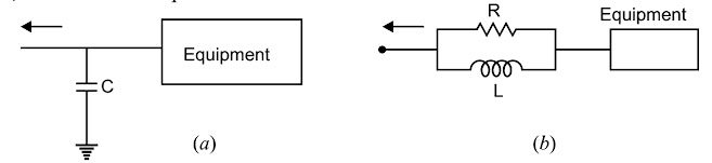
Ques.84. In an amplifier with the negative feedback, bandwidth is _______ and voltage gain is
- Bandwidth is decreased by factor (1 + Aβ) and voltage gain decrease
- Bandwidth is decreased by factor β and voltage gain remain same
- Bandwidth is increased by the factor (1 + Aβ) and voltage gain is reduced.✓
- Bandwidth remains the same and voltage gain increases.
Feedback is commonly used in amplifier circuits. A signal that is proportional to the output is compared with an input or a reference signal so that the desired output is obtained from the amplifier. The difference between the input and the feedback signals, called the error signal, is amplified by the amplifier. There are two types of feedback: In negative feedback, the signal that is fed back to the input side is known as the feedback signal, and its polarity is opposite that of the input signal (i.e., it is out of phase by 180° with respect to the input signal). So the input voltage applied to the basic amplifier is decreased and correspondingly the output is decreased. Hence, the voltage gain is reduced. This type of feedback is known as negative or degenerative feedback. The bandwidth with negative feedback increase by the factor (1 + Aβ) and gain decrease by the same factor. Where A is the open loop gain i.e gain without feedback β is the feedback factor Amount of feedback (1 + Aβ) is also called the desensitivity factor. Negative feedback in an amplifier has four major benefits: There are two disadvantages of negative feedback:
Ques.85. Choose the type of electrochemical cells from the following options.
1.1. Galvanic (that consume electrical energy)
1.2. Electrolytic (that consume electrical energy)
2.1. Galvanic (that produce and consume electrical energy)
2.2 Electrolytic (that produce electrical energy)
3.1. Galvanic (that produce electrical energy spontaneously)
3.2. Electrolytic (that consume electrical energy)✓
4.1. Galvanic (that produce electrical energy)
4.2. Electrolytic (that produce electrical energy)
Electrochemical cells are either ‘galvanic’ or electrolytic’. A ‘galvanic cell’ creates a potential difference across its terminals, through the process of charge separation by the release of energy due to the chemical reaction between its electrodes and the electrolyte Charge separation was explained in the earlier chapter on potential difference, and you may wish to review that chapter before continuing. An ‘electrolytic cell’, on the other hand, uses electricity to decompose its electrolyte, a process called ‘electrolysis’, usually for the purpose of electroplating – such as silver or chromium plating Put simply, a ‘galvanic cell’ produces electrical energy, whereas an ‘electrolytic cell’ uses or absorbs electrical energy.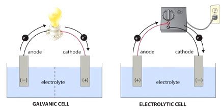
Ques.86. The flow of charged particle in one unchanging direction is called:-
- Sinusoidal Current
- Direct Current✓
- Alternating Current
- None of these
Electric Current The movement of electrons or charged particles produces electricity. metal conductors, electric current is produced only by the moving electrons. But in gases or in a solution of a salt, alkali or acid, the flow of to produces electricity. Direct Current When the direction of a current remains unchanged in a conductor, it is called Direct Current or D.C. In an electric cell, the positive and negative electrodes are fixed. And, the current flowing from a cell is D.C. Alternating Current An Alternating Current or A.C. is that electric current which changes direction every half of the time period.
Ques.87. ______ Is defined as the no. cycle completed by an alternating quantity in one second.
- Frequency✓
- Cycle
- Amplitude
- Instantaneous value
Frequency:- The number of cycles completed by the AC quantity in one second is called frequency. It is expressed in hertz (Hz) or cycles per second. As time period T is the time for one cycle, i.e. seconds/cycle and frequency is cycles/ second, we can say that the frequency is reciprocal of the time period. f = 1/T Hz Cycle:- One positive half-cycle and one negative half-cycle form a complete cycle. One cycle is equivalent to 2π radians. Instantaneous Value:- Instantaneous values are the values of the alternating quantities at any instant of time. They are represented by lowercase letters, i, v, e, etc. Amplitude:- The maximum magnitude of the quantity (voltage or current) is known as amplitude
Ques.88.The transmission ratio of the transformer is
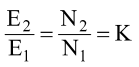
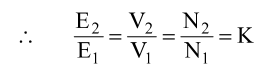
- K = V2/V1 = E2 = N2/N1
- K = V2/V1 = E2 = N2/N1✓
- K = V1/V2 = E2 = N2/N1
- K = V1/E1 = N1/E2 = V2/V2
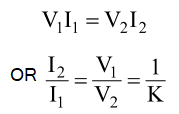
A transformer is a static device which converts the alternating current energy from one voltage level to another voltage level. Voltage Transformation Ratio (K) The constant K is called as Voltage transformation ratio and it is given as: For an ideal transformer, there is no voltage drop in the windings, therefore, E1 = E2and V1 = V2. If N2 > N1 and K >1 then the transformer is called as step up transformer. There are no losses in an ideal transformer therefore volt-ampere input of the primary will be always equal to the volt ampere of the secondary. From above equation, it is clear that current is inversely proportional to the voltage i.e if we will increase the value of voltage than the value of current will decrease.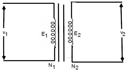
If N1 > N2 and K< 2 then the transformer is called as step down transformer.
Ques.89. Irrespective of the causes, which is the fault in a 3-phase system?
- Unsymmetrical fault
- Both symmetrical fault and Unsymmetrical faults✓
- Symmetrical faults
- External Faults
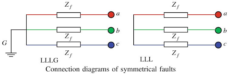
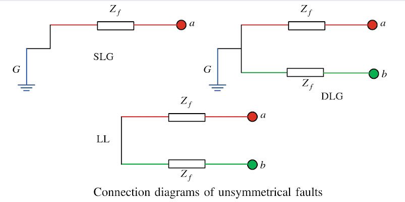
The fault in the power system is generally categorized into two type Symmetrical Fault The symmetrical faults are often known as balanced faults. In case of balanced faults, all three transmission lines are affected equally, and the system remains in the balanced condition. These types of faults are rare in the power system, and it contributes 2 % to 5 % of the total fault. These faults are easy to analyze. The symmetrical faults are classified as three lines to ground fault (LLLG) and three lines fault (LLL). The connection diagrams of symmetrical faults are shown in Fig. If the fault impedance, Zf = 0, then the fault is known as a solid or bolted fault. Unsymmetrical Faults The faults in the power system network which disturb the balanced condition of the network are known as unsymmetrical faults. The unsymmetrical faults are classified as the single line to ground faults (SLG), double line to ground faults (DLG 10%) and line to line faults (LL 15%). More than 90 % of faults occur in a power system are the single line to ground faults. The connection diagrams of different types of unsymmetrical faults are shown in Fig. Some of the examples of three-phase and three-phase to earth fault are as follows: In a three-phase, and three-phase to earth faults the current is the same because the fault current floe through the phase conductors only and cancels out. No current flows through the earth return path. Single-phase to earth fault is the most common fault and examples are: For three-phase circuits the highest fault current of all the above types of faults, is used to select the fault capacity of a device. In the vicinity of a generating station or generator, a single-phase to earth fault can be higher than a three-phase fault. For a single-phase circuit, a single-phase to earth fault current is used to decide the fault capacity of an equipment or device. For residential, commercial and industrial systems only three-phase and single-phase to earth fault are considered because generally these produce the highest fault current and are the most likely faults.
Ques.90. Switching surges, insulation failure, and resonance cause ______
- Overvoltage✓
- Both overvoltage and Low voltage
- Low voltage
- None of these
The over-voltages on a power system may be broadly divided into two main categories: INTERNAL CAUSES OF OVERVOLTAGES Internal causes of over-voltages on the power system are primarily due to oscillations set up by the sudden changes in the circuit conditions. This circuit change may be abnormal switching operation such as an opening of a circuit breaker, or it may be the fault condition such as the grounding of a line conductor. Switching Surge There are two kinds of over-voltages that threaten the insulation of the electric power system. One is the lightning surge. which determines the basic insulation level (BIL) of the insulation design, and the other is the switching surge caused by the circuit-breaker operation. There are many kinds of switching surges. They are a serious problem because the circuit breaker should protect the power system equipment from faults but its operation generates ar overvoltage that threatens the insulation. As the name suggests, switching means the sudden interruption in any circuit and surges means the overcurrent spikes that are caused in the circuit. Circuit-breaker operations that can cause switching surges include 1. Switching operation of an unload long transmission line and an unloaded transformer at a distant terminal 2. Switching operation of an un-load or reactor load transformer 3. Switching operation of a shunt reactor 4.Current chopping – Current chopping results in the production of high voltage transients across the contacts of the air blast circuit breaker. Over-voltages due to current chopping are prevented by resistance switching. Insulation failure – The most common case of insulation failure in a power system is the grounding of the conductor (i.e. insulation failure between line and earth) which may cause over-voltages. In case of a breakdown a insulation to earth, the potential at fault suddenly falls from maximum to zero and consequently a negative voltage wave of a very steep front in the form of surge travels from the fault in both the direction. Arcing ground – The phenomenon of intermittent arc taking place in line-to-ground fault of a 3 phase system with consequent production transients is known as arcing ground. The transients produced due to arcing ground are cumulative and may cause serious damage to the equipment in the power system by causing breakdown of insulation, Arcing-ground be prevented by earthing the neutral. Resonance – In the usual transmission lines, the resonance cannot occur at the fundamental supply frequency since the capacitance is usually very small. However, if the generator e.m.f wave is distorted, trouble may erupt due to the resonance of one of the higher harmonics. Resonance in an electrical system occurs when the inductive reactance of the circuit becomes equal to the capacitive reactance. Under resonance, the impedance of the circuit is equal to the inductance of the circuit and the p.f. is unity. Resonance causes high voltages in the electrical system.
Combined together, switching surges are the overcurrent/overvoltage spikes that are experienced in the highly inductive circuits at the time of sudden interruption i.e. switching period.


Amazing design mcq and it’s explanation
Thank you for your support
Best mcq and explanations
Thank you so much sir 🙏