Lead compensation and lag compensation are the most commonly used methods of compensation in the conventional frequency domain design of control systems.
Lag compensator
The transfer function of a lag compensator is given by
$G\left( s \right) = \frac{{\tau s + 1}}{{\beta \tau s + 1}}$
Where
$\beta = \frac{{{Z_c}}}{{{P_c}}} > 1$
Both pole and zero lie in LHS of the real plane but PC < ZC i.e. zero is farther away from the origin.
Lag Compensation adds a pole at origin (or for low frequencies).
It helps to reduce the steady-state error of the system.
An unstable system is a system that has at least one pole at the right side of the s-plane.
Even if we add a lag compensator to an unstable system, it will remain unstable.
Effects of phase-lag compensator:
Since the lag compensator allows high gain at low frequencies, it is basically a low pass filter. Therefore, it improves the steady-state performance.
In lag compensation, the attenuation characteristics are used for the compensation, whereas the phase lag characteristics are of no use in compensation.
Since the attenuation due to a lag compensator shifts the gain crossover frequency to a lower frequency point, the bandwidth of the system is reduced. Hence a slower response occurs. Therefore, rise time and settling time are usually longer and hence the transient response lasts for a longer time.
The system is very sensitive to parameter variation.
Since a lag compensator approximately acts as a proportional plus integral controller, it thus tends to make a system less stable.
52. The effects of the Addition of Zero are
Stability Increases
Setting Time increase
K Range Increase
All of the above
Answer.4. All of the above
Explanation:-
Result of Addition of Zero
All branches of RL now lie completely left half of the s-plane, so K can be adjusted to any positive value without causing instability.
By complete RL are now bent toward to LHS of s-plane from jω-axis.
By suitable adjustment of zero (compensating) along the negative axis, the steady-state error is within the limit.
The addition of zero in the transfer function causes lag compensation of the s-plane. A similar effect will result if a pair of complex-conjugate zero is added to the function.
The effects of the addition of zeros are as follows:
There is a change in the shape of the root locus and its shifts towards the left of the s-plane.
The stability of the system is enhanced.
Range of K increases.
Setting time speeds up.
53. Which of the following technique is not applicable to the nonlinear system?
Nyquist Criterion
Functional analysis
Phase-plane representation
Quasi linearization
Answer.1. Nyquist Criterion
Non-Linear system. A control system is called non-linear if it does not satisfy both the additive property and the homogeneous property. The transfer function cannot be defined for non-linear systems. It can be defined as linear systems only.
Nyquist Criterion:- It focuses also on the relative stability of the linear system. It is possible to determine the stability of a closed-loop pole from an open-loop pole without knowing the roots of the closed-loop system. A Nyquist plot is based on a polar plot. Nyquist criterion, Routh test, etc., are applicable to linear systems only.
Ques.54. In order to increase the damping of a badly underdamped system which of the following compensators may be used?
Phase-lead
Phase-lag
Lead-Lag
None of the above
Answer.1. Phase-lead
Explanation:-
Lead compensation:- The amplifier or the feedback network is modified so as to add a zero to the transfer function, thereby increasing the phase.
Effects of a lead compensation
The various effects of lead compensation are as follows:
Since a lead compensator adds a dominant zero and a pole, the damping of the closed-loop system is increased.
Less overshoot, less rise time, and less settling time are obtained due to the increase of damping and hence there is improvement in the transient response.
It improves the phase margin of the closed-loop system.
Improvement of gain and phase margins and hence the relative stability occurs due to the reduction in the slope of the magnitude plot in a Bode diagram of the forward path transfer function at the gain crossover frequency.
The bandwidth of the closed-loop system is increased and hence the response is faster.
The steady-state error does not get affected.
Ques.55. Which of the following is the limitation of Lead compensation?
Larger gain required
More Bandwidth
Conditionally stable system
All of the above
Answer.4. All of the above
Explanation:-
Limitations Of a lead compensation
The various limitations of the lead compensation are as follows:
Since an additional increase in gain to offset the attenuation inherent in the lead network is required, the effect of a larger gain requirement in most of the cases implies larger space, more elements, greater weight, and higher cost.
The noise entering the system is more susceptible to the noise signals due to an increase in the high-frequency gain and hence more bandwidth is sometimes not desirable.
Since the compensated system may have a larger undershoot than overshoot, there is the tendency to overcompensate a system, which may lead to a conditionally stable system.
From a single lead network, the maximum lead angle available is about 60°. For leads of more than 70° to 90°, a multistage lead compensator is required.
56. The Transportation lag is also called as
Dead zone
Grey Zone
Grey Time
Deadtime
Answer.4. Dead time
Explanation:-
The transportation lag is the delay between the time an input signal is applied to a system and the time the system reacts to that input signal. Transportation lags are common in industrial applications. They are often called “dead time”
57. The phase lag produced by transportation relays
Is independent of frequency
Is inversely proportional to frequency
Increases linearly with frequency
Decreases linearly with frequency
Answer.3. Increases linearly with frequency
Explanation:-
The name phase-lag system comes from the fact that a sinusoidal input causes a sinusoidal output, but with a phase lag. The reason why such a system is alternatively called a lowpass is that higher-frequency sinusoidal input signals are attenuated with increasing frequency.
The transfer function of the phase-lag relay is
[katex]G(s) = \frac{{1 + aTs}}{{1 + Ts}}[/katex]
The transfer function of the phase-lag controller has a real zero at s = −1/aT and a real pole at s= −1/T. Since a is less than unity, the pole is always located to the right of the zero.
Since the phase-lag compensator adds a negative phase angle to a system, the phase lag is not a useful effect of the compensation and does not provide a direct means of improving the phase margin. The phase-lag compensator does, however, reduce the gain and so can be used to lower the crossover frequency. A consequence of this is that, as usual, the phase margin of the system is higher at the lower frequency, the stability can be improved.
Hence the phase lag produced by transportation relays Increases linearly with frequency.
58.In a stable control system saturation can cause which of the following?
Low-level oscillations
High-level oscillations
Conditional stability
Overdamping
Answer.1. Low-level oscillations
Explanation:-
In stable control, systems backlash is the form of the error that may cause a low level of oscillations and hence can be useful sometimes as it increases the damping.
In a servo system, the gear may cause low-level oscillations or chattering phenomena, and the system may even turn unstable for large backlash.
59. Which of the following can be measured by the use of a tacho generator?
Acceleration
Speed
Speed and acceleration
Displacement
Answer.2. Speed
Explanation:-
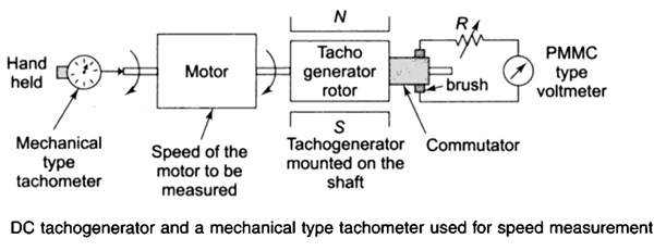
A tachometer is used to measure the speed of rotation of a rotating body like an electric motor. Tachometers can be of the mechanical type or electromagnetic type. Mechanical type tachometers are brought in contact with the rotating shaft from the side and the speed of rotation is recorded on the calibrated dial as has been shown in Fig. Electromechanical type tachometers are called tacho-generators. The figure shows a tacho generator used to measure the speed of an electric motor. The dc tacho generator is a small dc generator mounted on the shaft of the motor. It is a permanent magnet dc generator.
Tacho-generator is an example of a closed-loop control system.
60. ______is not a final control element.
Control valve
Potentiometer
Electro-pneumatic converter
Servomotor
Answer.2. Potentiometer
Explanation:-
Final control element:- A final control element is defined as a mechanical device that physically changes a process in response to a change in the control system setpoint. Final control elements relevant to actuators include valves, dampers, fluid couplings, gates, and burner tilts to name a few. Final control elements are an essential part of process control systems, allowing an operator to achieve a desired process variable output by manipulating a process variable setpoint.
A potentiometer is a resistive-type transducer that converts either linear or angular displacement into an output voltage by moving a sliding contact along the surface of a resistive element.
Potentiometers are commonly used to control electrical devices such as volume controls on audio equipment. Potentiometers operated by a mechanism can be used as position transducers, for example, in a joystick. Potentiometers are rarely used to directly control significant power (more than a watt), since the power dissipated in the potentiometer would be comparable to the power in the controlled load
Generators are used as control elements in control systems rather than as transducers.
q6- explaination -why open loop system is more accurate is wrong..
because open loop system are not accurate n reliable because their accuracy depend on accuracy of calibration.


Q 4 Answer should be option 2 increase
q6- explaination -why open loop system is more accurate is wrong..
because open loop system are not accurate n reliable because their accuracy depend on accuracy of calibration.