Ques.61. A circuit having the power factor of 0.8 consumes 20 W. What is the value of reactive power (in VAR) of the circuit? (SSC 2018 S-2)
10
15
20
25
Answer.1. 10
Explanation
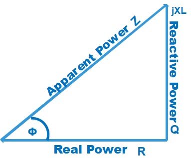
The power triangle or Impedance triangle of the AC circuit is shown Below
Cosφ = Base ⁄ Hypotenuse = Active Power ⁄ Apparent Power Active Power = Apparent power × Cosφ Sinφ = Perpendicular ⁄ Hypotenuse = Reactive Power ⁄ Apparent Power
Reactive Power = Apparent power × Sinφ
or
Reactive Power = (Active Power × Sinφ) ⁄ Cosφ
cosφ = 0.8
Sin2φ = 1 − cos2φ
Sin2φ = 1 − (0.8)2
Sinφ = 0.6
Reactive Power =(20 × 0.6) ⁄ 0.8
Reactive Power = 15 VAR
Ques.62. Two incandescent lamps of wattage 40W, 60 W are connected in series with the voltage of 230 V. Which out of the two lamps will glow brighter? (SSC 2018 S-2)
40 W
60 W
Both brightly
Both dim
Answer.1. 40 W
Explanation
Comparing the 60W bulb to a 40W bulb means that the 60W bulb consumes 20W more power than the 40W bulb. Now note the question its a 40W and 60W bulbs we talking about, not resistors! For the bulbs, wattage is brightness. The 40W and 60W bulbs will be rated for a particular (I mean same) voltage, not different. So considering power P=V2/Rpower is inversely proportional to resistance (bulbs rated for the same voltage). Which means that the 40W bulb has more resistance across it compared to the 60W bulb. ( Compare in terms of brightness, a 0W bulb has to glow so dim just because it has high resistance while a 100W bulb glows very much bright because its resistance is low)
Connecting the 2 bulbs in series implies that the current is the same, hence the power consumption totally depends on how voltage gets divided between the bulbs. Naturally, the 40W bulb will have more voltage across it since it has more resistance. Hence, the 40W bulb will glow brighter.
Ques.63. Which of the following is the dimensional formula for conductance or conductivity? (SSC 2018 S-3)
M−1 L−2 T3 A2
M L3 T−3 A−2
M2 L2 T−3 A−2
M L2 T3 A−2
Answer.1. M−1 L−2 T3 A2
Explanation
The conductance is given as
Conductance = 1 ⁄ Resistance
Firstly consider the resistance.
Ohm’s law states that electric current flowing through the conductor is directly proportional to the potential difference between its two ends when the temperature and other physical parameters of the conductor remain unchanged.
V = IR
⇒ R = VI
Now V has units of (electric field)*(distance).
But the electric field has units (force)/(charge).
Also, charge has dimensions of (current)(time) and force has dimensions (mass)(length)/(time)2.
Thus, dimensions of V is,
[V] = LMLT−2 ⁄ AT
⇒ [V] = M L² T ⁻³ A⁻¹
Dimensional formula for I = A
Put these values in equation (1), we get:
The dimensional formula for R = M L2 T−3 A−1/ A
Dimensional formula for R = [M L2 T −3 A−2]
Now the Dimensional formula of conductance will be
G = 1 ⁄ [M L2 T −3 A−2]
G = [M−1 L−2 T3 A2]
Ques.64. Which of the following is the CORRECT expression for the capacitance of a parallel plate capacitor? (SSC 2018 S-3)
εA/d
εA2/d
εA2d2
A2d2/ε
Answer.1. εA/d
Explanation
The capacitance C of a capacitor is the ratio of the magnitude of the charge on either conductor (plate) to the magnitude of the potential c^lif^rerence between the conductors (plates).
C = Q/V
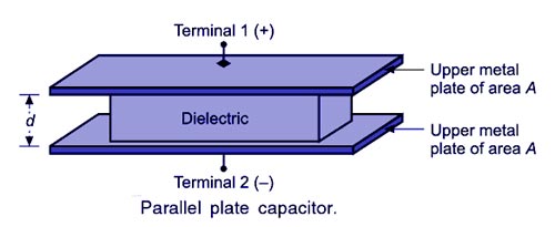
THE PARALLEL-PLATE CAPACITOR
The figure shows the structure of a parallel plate capacitor. It is made up of two parallel plates of the area of cross-section A, kept in an insulating medium and separated from each other by a distance of d metros. Then, if the two plates are applied with potential, one of the plates will be positively charged and the other negatively charged.
Let the charge on the plates were given by Q coulombs.
The capacitance of a device depends on the geometric arrangement of the conductors. The capacitance of a parallel-plate capacitor with plates separated air can be easily calculated from three facts.
The magnitude of the electric field between two plates is given E = σ/εo, where σ is the magnitude of the charge per unit area on each plate and εο = Permittivity of free space = 8.85 × 10⁻¹²
Second, the potential difference between the two plates is ΔV = Ed, where d is the distance between the plates.
Third, the charge one plate is given by q = σA, where A is the area of the plate. Substituting the three facts into the definition of capacitance gives the desired result:
Ques.65. In a series combination of several inductors, the equivalent inductance is______ (SSC 2018 S-3)
Equal to the largest inductance of the combination
Lower than the largest inductance of the combination
Lower than the smallest inductance of the combination
Greater than the largest inductance of the combination
Answer.4. Greater than the largest inductance of the combination
Explanation
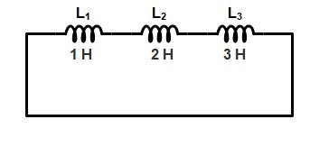
Let us Suppose that the three Resistance L1, L2, L3 of 1 Henry, 2 Henry, and 3 Henry are connected in series respectively.
Now add all the inductance of the circuit we get
Leq = L1 + L2 + L3 Leq = 1 + 2 + 3 = 5H
Now from the above result, we can conclude that the equivalent Inductance in the series combination is greater than the largest Inductance in the combination (since the largest Inductance was 3H).
Therefore, the Option.4. is correct.
Ques.65. Which of the following is the reciprocal of the resistivity? (SSC 2018 S-3)
Reluctivity
Susceptibility
Conductivity
Permittivity
Answer.3. Conductivity
Explanation
Resistivity:-
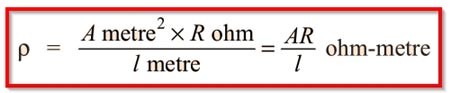
The resistance of a material having unit length and the unit cross-sectional area is known as Specific Resistance or Resistivity.
In the S.I. system of units
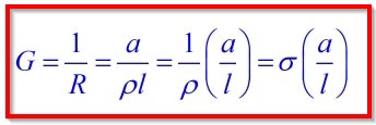
Conductivity
The electrical resistance of an electrical conductor is a measure of the difficulty to pass an electric current through that conductor. The inverse quantity is electrical conductance or conductivity and is the ease with which an electric current passes. Electrical conductance is measured in siemens (S) σ and denoted by (G).
The material having a high value of conductivity is a good conductor of electricity while the material having the low value of conductivity is a good insulator.
Ques.66. Determine the value of equivalent inductance, if 4 inductors having inductance L are connected in parallel. (SSC 2018 S-3)
4L
L/4
4/L
8L
Answer.2. L/4
Explanation
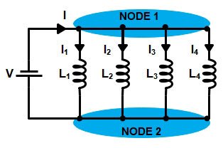
Inductors are sometimes connected in parallel in a circuit. Two or more circuit elements are said to be in parallel when they share the same pair of nodes. In a parallel circuit, the voltage across each of the parallel circuit elements is the same, but the current through each of the elements might be different. Let us consider four inductors that are connected in a parallel to a source voltage V as shown in Fig. In these cases, the voltage across each of these resistors will be V.
Note:- Inductor connected in parallel combine the same way as the resistor in parallel.
According to Ohm’s law, the currents the current I1, I2, I3, I4 through the corresponding inductors L1, L2, L3 & L4 can be written as
Ques.67. Determine the conductance (in Siemens) of a conductor, when the potential difference between the ends of the conductor is 30 V and the current flowing through the conductor is 3A. (SSC 2018 S-3)
0.1
1.1
2.4
4.2
Answer.1. 0.1
Explanation
Conductance “G” is measured in Siemens and it is the reciprocal the resistance
G = 1/R = G = 1/V/I
G = I/V
Where
I = current = 3A
V = voltage = 30V
G = 3/30 = 0.1 Siemens
Ques.68. How much power will be dissipated by a 10 ohms resistors, when the current through the resistor is 3A? (SSC 2018 S-3)
30
40
60
90
Answer.4. 90
Explanation
Given
Resistance R = 10Ω
Current I = 3 A
Power dissipated by the resistor is
P = I2R
P = 32 × 10
P = 90 watts
Ques.69. Determine the value of resistance (in ohms) of a resistor at 40 degrees Celsius, when the resistance of 10 ohms at 0 degree Celsius and the temperature coefficient at 0 degree Celsius is 0.04. (SSC 2018 S-3)
20
23
24
26
Answer.4. 26
Explanation
Resistance Temperature Coefficient:
The change in resistance of a material with the increase in temperature can be expressed b means of the temperature coefficient of resistance. Consider a conductor having resistance Ro at 0°c and Rt at t°c. From the above discussion, we can conclude that the change in the resistance i.e (Rt – Ro) is
Directly proportional to the initial resistance Ro
Directly proportional to the rise in temperature t°c.
Depends on the nature of the material for conductor metals and alloy
Hence
(Rt – Ro) ∝ Rot
(Rt – Ro) = αRot
Rt = Ro(1 + αot)
Where αo is constant and called as the temperature coefficient of resistance at 0°c and its value depends upon the nature of material and temperature.
Ro = 10 ohms
T = 40°
α =.04
RT = ?
Hence the value of resistance at 40°C is
RT = 10(1 + .04 × 40)
RT = 26 Ω
Ques.70. Determine the energy stored (in J) by a 5 H inductor, when the current flowing through the inductor is 6A. (SSC 2018 S-3)
94
90
60
40
Answer.2. 90
The energy stored in the magnetic field of an inductor can be expressed as
Hi, thank you for such a brilliant post. I have been reading some blogs that gives me more knowledge about ssc je basic electrical questions 2009-2018 solved . I must say this is one of the best among them. You have done a great research for I feel, thanks for sharing.They offer same information here Bencableelectrical.co.nz one must check them also.

Thank you
Thank you
Thank you
Hi, thank you for such a brilliant post. I have been reading some blogs that gives me more knowledge about ssc je basic electrical questions 2009-2018 solved . I must say this is one of the best among them. You have done a great research for I feel, thanks for sharing.They offer same information here Bencableelectrical.co.nz one must check them also.