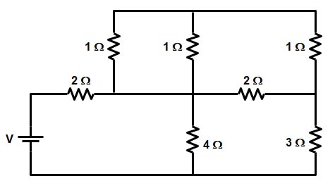
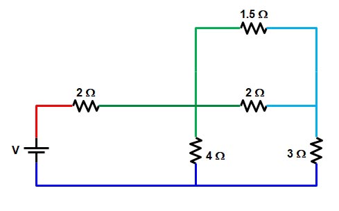
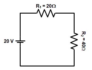
Ques.71. Determine the equivalent resistance (in ohms) for the circuit given below. (SSC 2018 S-3)
2
4
6
9
Answer.2. 4
Explanation
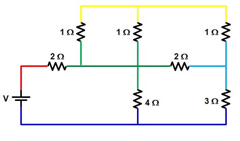
To identify whether the resistance is connected in series or in parallel consider the following method
Use one color for each continuous wire
DO NOT cross any circuit elements
Any element that shares the same two colors are in parallel
Now the circuit will look as shown below
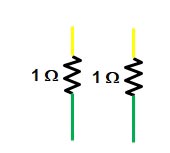
As you can see from the above figure the two resistance of 1 ohms each share two common colors i.e yellow and green hence this two resistance are in parallel.
1Ω II 1Ω = (1 × 1) ⁄ (1 + 1) = 0.5 Ω
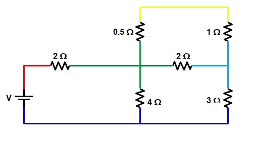
Again redraw the circuit as shown in figure
Now the yellow wire is connected to only the resistance of 0.5 Ω & 1 Ω hence this two resistance are in series,
R = 0.5 + 1 = 1.5 Ω
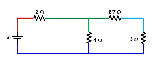
Now again redrawing the circuit we get
From the above figure, it is clear that the resistance 1.5 Ω and resistance 2 Ω share same two colors i.e green and sky blue therefore this two resistance are connected in the series.
R = 1.5 || 2 = ( 1.5 × 2) ⁄ (1.5 + 2)
R = 6/7 Ω
Again redrawing the circuit we get
The sky blue wire is connected to the only resistance 6/7 Ω and 3Ω hence they both are connected in series, therefore,
R = 6/7 + 3 = 27 ⁄ 7 Ω
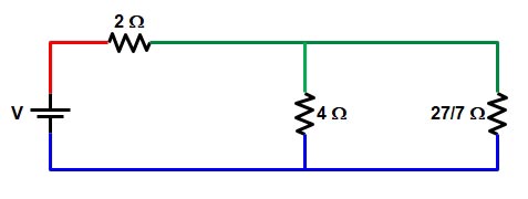
Redraw the given circuit
The resistance 4 Ω and the resistance 27/7 Ω is connected to the same wire i.e green and blue hence this two resistance are connected in parallel
R = 4 || 27/7 = ( 4 × 27/7) ⁄ (4 + 27/7) = 1.96 Ω
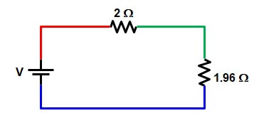
Now the final circuit is shown below
Now the green wire is connected to the only resistance of 2 Ω & 1.96 Ω
R = 2 + 1.96 = 3.96 ≅ 4Ω
Ques.72. Determine the resistance (in Ohms) of a resistor when the potential difference between the ends of the resistors is 24 V and the current flowing through the resistors is 3 A. (SSC 2018 S-3)
12
10
8
4
Answer.3. 8
Explanation
The resistance of the conductor or an element is defined as the ratio of the potential difference between the end of the conductor (V) to the current flowing in the conductor I
R = V/I
Where
V = Voltage of the resistor = 24 V
I = current = 3 A
R = 24/3 = 8Ω
Ques.73. Which of the following statement is TRUE? (SSC 2018 S-3)
The current always flows in the directions of current
The current always flows opposite to the direction of flows of electrons
The current always flows from the positive terminal to negative terminals
The current always flows from the negative terminal to positive terminals
Answer.2. The current always flows opposite to the direction of flows of electrons
Explanation
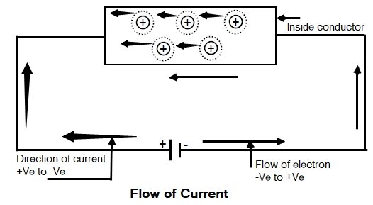
Concept of current and Electromotive force
Consider a conductor that has large numbers of free electrons moving in the random direction. Now when we apply an external source to the conductor, then all free electrons drift along the conductor in a particular direction. The direction of the electrons will depend upon how the external source is applied to the conductor.
Hence the electrical source required to drift the free electron in a particular direction in a given conductor is called an electrical Electromotive Force.
As we know that the free electrons are negatively charged, when the external source is applied (such as the cell) then free electrons get attracted by the positive of the cell connection. Therefore the electrons get aligned in the particular direction under the influence of an electromagnetic force.
An ion is an electrically charged particle produced by either removing electrons from a neutral atom to give a positive ion or adding electrons to a neutral atom to give a negative ion. When an ion is formed, the number of protons does not change.
When the free electron gets dragged towards positive from an atom it becomes the positively charged ion. Such positive ion drags a free electron from the next atom. This process repeats from atom to atom along the conductor. So there is the flow of electrons from negative to positive of the cell. This movement of electrons is called an electric current. The movement of electrons is always from negative to positive whereas the movement of current is assumed as positive to negative.
The electrons in a circuit flow in the opposite direction to the electric current. It is a nuisance to have to remember this. It stems from the early days of experiments on static electricity. Benjamin Franklin realized that there were two types of electric charge, which he called positive and negative. He had to choose which type he would call positive, and his choice was to say that, when amber was rubbed with a silk cloth, the amber acquired a negative charge. Franklin was setting up a convention, which other scientists then followed – hence the term conventional current. He had no way of knowing that electrons were being rubbed from the silk to the amber, but his choice means that we now say that electrons have a negative charge.
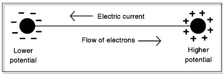
It is our common observation that water flows from a place at a higher level to a place at a lowe potential or level irrespective of the amount of water at the two levels. Heat flows from a body at; higher temperature to a body at a lower temperature irrespective of the amount of heat contained by the two bodies. Similarly, electric charges move from one point to another if there exists a difference in the electric potential irrespective of the concentration of charges at the two points. Thus electric potential determines the direction of the flow of electric current. Charge flows from a body at a higher potential to a body at a lower potential. By convention, a positively charged body is always at a higher potential as compares to a negatively charged body. If positive charges like protons or positive ions are free to move they would move from a higher potential point to a lower potential point.
A difference in potential implies the existence of an electric field whose direction is from higher to lower potential. A negative charge experiences a force F = -q E. The negative sign makes it move in a direction opposite to that of E (Electrical field). Thus the electron moves from a lower potential to higher potential regions.
Ques.74. Which of the following expression explain’s the Kirchhoff’s current Law? (SSC 2018 S-3)
Where M is the total number of branches with currents flowing towards or away from the node and INrepresent the current in the Nth branches
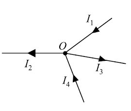
An algebraic sum is one in which the sign of the quantity is taken into account. For example, consider four conductors carrying currents I1, I2, I3, & I4 and meeting at point O as shown in Fig
If we take the signs of currents flowing towards point O as positive, then currents flowing away from point O will be assigned negative sign. Thus, applying Kirchhoff’s current law to the junction O we have,
i.e., Sum of incoming currents = Sum of outgoing currents.
Therefore, Kirchhoff’s current law may also be stated as under:
The sum of currents flowing towards any junction in an electrical circuit is equal to the sum of currents flowing away from that junction. Kirchhoff’s current law is rightly called the junction rule.
Kirchhoff’s current law is true because electric current is merely the flow of free electrons and they cannot accumulate at any point in the circuit. This is in accordance with the law of conservation of charge. Hence, Kirchhoff’s current law is based on the law of conservation of charge.
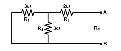
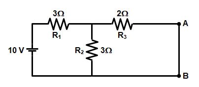
Ques.75. Determine the Norton’s Resistance (in Ohms) between terminals A and B for the circuit given below. (SSC 2018 S-3)
6.5
5.4
4.5
3.5
Answer.4. 3.5
Explanation
To find the Norton resistance first we have to reduce the circuit.
The two resistances 2 ohms are in parallel and in series with another 2-ohm resistance i.e
Now again the two resistance of 1 ohm each are in series with each other
= 1 + 1 = 2 ohms
Now To determine Norton’s Equivalent circuit Resistance RN, all the voltage source are replaced by the Short circuit as shown in the figure
Norton equivalent resistance for the given network is
R = (R1 || R2) + R3
R = (3 || 3) + 2 = (3 x 3) ⁄ (3 + 3) + 2 = 3.5Ω
Norton equivalent resistance = 3.5Ω
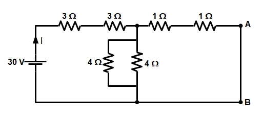
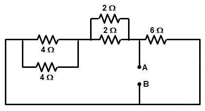
Ques.76. Determine the value of current I (in A) drawn from the voltage source for the circuit given below. (SSC 2018 S-3)
2.5
3.4
4.3
6.5
Answer.3. 4.3
Explanation
In the given circuit the resistance 3Ω & 3Ω and the resistance 1Ω and 1Ω are in series with each other while the resistance 4Ω and 4Ω are in parallel to each other.i.e
R1 = 3Ω + 3Ω = 6Ω
R2 = 4Ω || 4Ω = (4 × 4) ⁄ (4 + 4) = 2Ω
R3 = 1Ω + 1Ω = 2Ω
Now from the above circuit, it is clear that the resistance R2and R3 are in series with the resistance R1.
R = R1 + (R2 || R3)
R = 6 + ( 2 || 2)
R = 6 + (2 × 2) ⁄ (2 + 2)
R = 6 + 1 = 7Ω
Now current I = V/R
I = 30/7 = 4.28 A
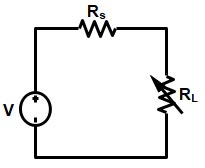
Ques.77. Determine the value of source resistance (in Ohms) for the transmitting maximum power from the source to the load, when the load impedance of the circuit is 10 − j2 Ohms. (SSC 2018 S-3)
2
10
−2
−10
Answer.2. 10
Explanation
For maximum power transfer, the impedance of the load must be equal to the complex conjugate of the impedance of the output. Thus, if the output impedance of a network has the value R + jX, for maximum power transfer, the load should have an impedance of R – jX. This implies that, if the output impedance has a capacitive component, the load must have an inductive component to obtain maximum output power. It can be seen that the simpler statement given above is a special case of this result in which the reactive component of the output impedance is zero. Hence for maximum power transfer, load impedance must be equal to the complex conjugate of Source impedance
As we know that The impedance of input of something to which a signal is applied is a measure of how much power that input will tend to draw (from a given output voltage). This impedance is known as the load impedance.
Therefore Zs = ZL*
Zs = (10 − j2)*
Zs = (10 + j2)Ω
Hence the value of source resistance is 10Ω and the value of source reactance is 2Ω
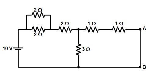
Ques.78. Determine the power (in W) delivered from the source for the circuit given below. (SSC 2018 S-3)
23.8
26.6
24.6
22.6
Answer.1. 23.8
Explanation
The two resistances 2 ohms are in parallel and in series with another 2-ohm resistance i.e
Now again the two resistance of 1 ohm each are in series with each other
= 1 + 1 = 2 ohms
Now from the above circuit, it is clear that the resistance R2and R3 are in series with the resistance R1.
R = R1 + (R2 || R3)
R = 3 + ( 3 || 2)
R = 3 + (3 × 2) ⁄ (3 + 2)
R = 3 + 1.2 = 4.2Ω
Now current I = V/R
I = 10/4.2 =2.38 A
Power delivered from the source
P = I2R
P = (2.38)2 × 4.2
P = 23.79 ≅ 23.8
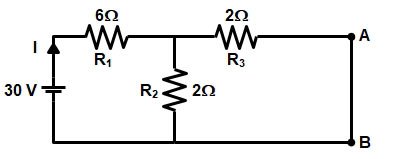
Ques.79. Determine the value of Thevenin’s equivalent resistance (in Ohms) across terminal A and B for the electrical circuit given below. (SSC 2018 S-3)
2
6
8
1
Answer.1. 2
Explanation
To determine the Thevenin’s Equivalent circuit Resistance Rth, all the voltage source are replaced by the Short circuit as shown in the figure below
Now solving the circuit, the resistance 4Ω and 4Ω are in series with the resistance of 2Ω and 2Ω
R = (4 || 4) + (2 || 2)
R = ( 4 × 4) ⁄ (4 + 4) + ( 2 × 2) ⁄ (2 + 2)
R = 2 + 1 = 3Ω
Now the Thevenin’s Resistance RTH is
RTH = 3 || 6 = ( 3 × 6) ⁄ (3 + 6)
RTH = 2Ω
Ques.80. Determine the value of load resistance (in ohms) for a circuit, when the maximum power transferred from the source of 50 V to the load is 25 W. (SSC 2018 S-3)
50
40
35
25
Answer.4. 25
Explanation:-
Maximum Power TransferTheorem
Maximum Power Transfer Theorem can be stated as – A resistive load is connected to a DC network, receives maximum power when the load resistance is equal to the internal resistance known as (Thevenin’s equivalent resistance). The maximum power transfer theorem is applied to both the DC and AC circuit. The only difference is that in an AC circuit the resistance is substituted by the impedance.
Let V be the voltage source, Rs be the internal resistance of the source and RL be the load resistance or the Thevenin resistance.
Hi, thank you for such a brilliant post. I have been reading some blogs that gives me more knowledge about ssc je basic electrical questions 2009-2018 solved . I must say this is one of the best among them. You have done a great research for I feel, thanks for sharing.They offer same information here Bencableelectrical.co.nz one must check them also.


Thank you
Thank you
Thank you
Hi, thank you for such a brilliant post. I have been reading some blogs that gives me more knowledge about ssc je basic electrical questions 2009-2018 solved . I must say this is one of the best among them. You have done a great research for I feel, thanks for sharing.They offer same information here Bencableelectrical.co.nz one must check them also.