
Ques.31. In which of the following voltage sources is the movement of conductors in a magnetic field used to produce voltage? (SSC-2016)
- Transformer
- D.C Motor
- D.C generator
- Zinc-copper element
Answer.3. D.C generator Explanation:- A DC generator is a rotating machine that converts mechanical energy into electrical energy. This conversion is accomplished by rotating an armature, which carries conductors, in a magnetic field, thus inducing an emf in the conductors. For an emf to be induced in the conductors a relative motion must always exist between the conductors and the magnetic field in such a manner that conductors cut through the field. In most DC generators, the armature is the rotating member and the field is the stationary member. A mechanical force is applied to the shaft of the rotating member to cause the relative motion. Thus, when mechanical energy is put into the machine in the form of a mechanical force or twist on the shaft, causing the shaft to turn at a certain speed, electrical energy in the form of voltage and current is delivered to the external load circuit.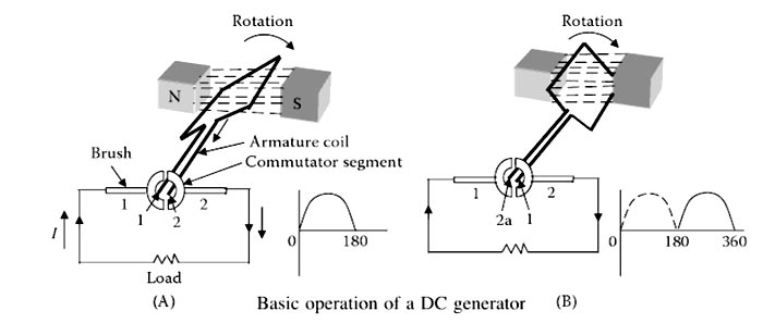
Ques.32. Interpoles are used in (SSC-2016)
- Wave wound machine
- Lap wound machine
- Both lap and wave wound machine
- None of the above
Answer.3. Both lap and wave wound machine Explanation:- Main Functions of the Interpole
Ques.33. The waveform of the armature m.m.f. in DC machine is (SSC-2016)
- Triangular
- Square
- Rectangular
- Sinusoidal
Answer.1. Triangular Explanation:- The armature MMF of a distributed armature winding of a dc machine is triangular in shape as shown in Fig. In a D.C. machine, the armature M.M.F. wave has its maximum value at fixed points between the main poles, and its chief effect is to increase the flux density on one side of the pole and reduce it on the other At GNA (Geometrical neutral axis) MMF Attends it’s maximum value MMF and at MNA ( Magnetic neutral axis) MMF Attends zero value, it is alternating in nature. At MNA axis the armature conductors are situated in parallel with the field flux thus induced EMF is zero at that time and at GNA axis the armature conductors are situated at 90 ° with the field fluxes, between MNA and GNA the armature MMF slowly rise as the angle between an armature conductor and field flux increases the MMF induced on that conductor increases thus it creates a triangular form of armature MMF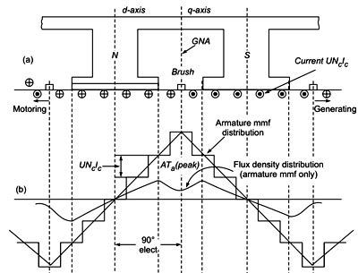
Ques.34. The current flowing in the conductors of a DC motor is (SSC-2016)
- D.C
- A.C
- D.C as well as A.C
- Transients
Answer.2. A.C Explanation:- In a DC motor, a conductor (armature) is located between the north and south poles of a stationary magnet (field structure). A commutator is used to reverse the direction of the current, helping transmit current between the power source and armature. The armature is a cylindrical device attached to a driveshaft that is designed to become an electromagnet when current is passed through it. During operation, the armature rotates through the magnetic fields. At set intervals, the rotation cuts across the magnetic fields, reversing current flow. This process occurs on each half rotation of the armature. The field structure provides a magnetic field for the armature to move through. Magnetic fields are composed of lines of force. In DC motors, the terms field structure, field magnet, and field coils may be used to represent the stationary magnet. When D.C supply passes through the conductor in a DC motor, the conductor becomes an electromagnet and generates another magnetic field inside the original lines of force. As the twin fields increase in intensity, they strengthen each other and push against the conductor. The current and these strong magnetic fields determine the direction of rotation in a DC motor. Note:- If A.C supply is given to the DC motor then the Series Connection: Parallel connection: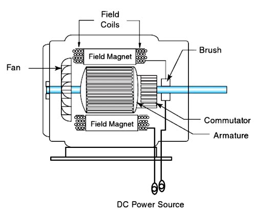
where k = number of poles and the number of turns in the winding.
Φ = flux per pole
i = current.
Therefore, Torque = k × Ia2
Ques.35. DC shunt generator has (SSC-2016)
- Slightly drooping characteristic curve
- Appreciably rising characteristic
- Constant voltage characteristic
- Appreciably falling characteristic
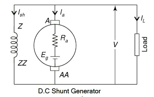
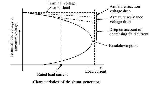
Answer.1. Slightly drooping characteristic curve Explanation:- The electrical equivalent circuit of a long shunt compound generator is shown in Fig. The shunt field winding is connected across the series combination of armature and series field windings and across the load. This is characterized by the fact that the series field current equals the armature current. The terminal voltage of the generator decreases on loading. This is because of In the case of a dc shunt generator, the field circuit is connected directly across the armature. With the increase in the load current, the voltage drops as a result of armature reaction and internal resistance of the armature circuit are increased and therefore the terminal voltage decreases. Hence the field current decreases. As a result, the terminal voltage drops further. At no-load, the terminal voltage is the same as the generated voltage. The effects of armature reaction, armature circuit voltage drop, and the decrease in field current are all shown in Figure. against the increase in load current. The effects of both the armature reaction and the armature resistance voltage drop are shown as dashed straight lines in Figure. These dashed lines represent linear voltage decreases directly proportional to the increase in load current. The drop owing to decreased field current is represented by the curved line since it depends on the degree of field flux saturation at that value of the load. It can be seen from Figure that the terminal voltage decreases with load current only to a small extent up to its rated load current value. Thus, the shunt generator produces a fairly constant output voltage with the application of load. If the further application of load continues, it causes the generator to reach a breakdown point where the armature reaction effect becomes so severe that the terminal voltage drops to a great extent and as a result, the generator cannot draw any larger load current. The load current, in fact, also drops.Characteristics of DC Shunt Generator
Ques.36. An e.m.f. is induced in the windings of an armature of a DC generator when the armature rotates in (SSC-2016)
- Alternating magnetic flux
- Magnetic field
- Electrostatic field
- Electromagnetic flux
Answer.2. Magnetic field Explanation:-
Ques.37. The function of a commutator in a DC generator is. (SSC-2016)
- To collect current from conductors
- To change DC into a.c.
- To conduct the current to the brushes
- To change A.C. into D.C
Answer.4. To change A.C. into D.C Explanation:- The commutator is one of the very important parts of dc machine which rotates with the armature. The function of the commutator is to convert alternating currents induced in the armature conductors into direct currents in the external circuit in case of generator operation. In the case of a dc motor, the function of the commutator is to produce a unidirectional torque. The commutator also helps to keep the magnetic flux stationary in space.
Generally, the alternating voltage is produced in the coil, which is rotating in a magnetic field, but the direct current is required in the external circuit. For this purpose, the commutator is needed. Each commutator segment is connected to the ends of the armature coils. The commutator receives the current from the brushes, which are also placed on the rotating armature
Ques.38. The speed of a DC shunt motor is required to be more than F.L(Full Load) speed. This is possible by ___________. (SSC-2016)
- Increasing the armature current
- Decreasing the armature current
- Increasing the excitation current
- Reducing the field current
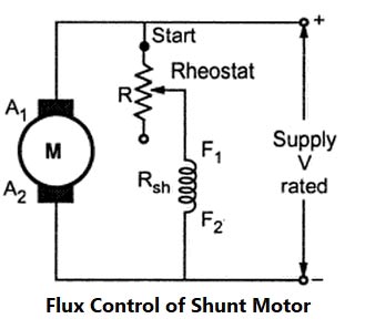
Answer.4. Reducing the field current Explanation:- The speed of DC shunt can be controlled by various Method such as The speed of DC Shunt Motor is inversely proportional to the flux. The flux is dependent on the current through the shunt field winding. Thus flux can be controlled by adding a rheostat (variable resistance) in series with the shunt field winding. At Starting the rheostat R is kept at the minimum. The supply voltage is at its rated value. So the current through shunt field winding is also at its rated value. Hence the speed is also rated speed i.e at normal speed. When the resistance R is increased due to which shunt field current Ish decreases, hence decreasing the flux produced. As N =(I/Φ), the speed of the motor increases beyond its rated value. Now as we know that the speed of DC motor is directly proportional to the flux hence when the speed is increased the back EMF also increased. Thus by this method, the speed control above the rated value is possible.
Flux Control Method
Ques.39. The rotating part of a DC motor is known as ______ (SSC-2016)
- Pole
- Stator
- Armature
- Carbon Brush
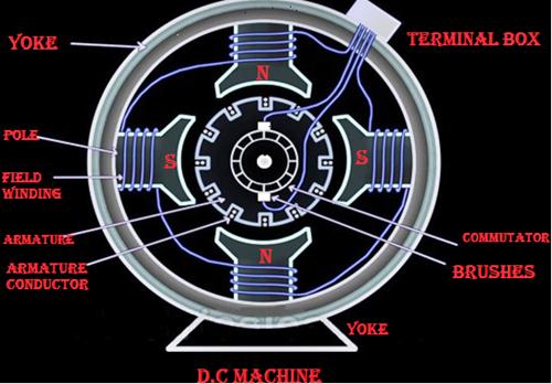
Answer.3. Armature Explanation:- Armature of D.C Machine The armature is the rotating part of the dc machine. The armature of the dc machine consists of a shaft upon which a laminated cylindrical core is mounted called armature core. The armature core has slots in its outer surface. The laminations are insulated from each other and tightly clamped together. The purpose of using these laminations are to minimize the eddy circuit loss. The armature is one of the very important requirements of a dc machine without which the whole operation results in failure. Basically, two types of windings are used in dc machine, they are lap and wave winding. Field system The magnetic field system is a stationary part of the d.c. machine. The main purpose of the field system is to produce a uniform magnetic field in the air gap, within which the armature rotates. Electromagnets are preferred in comparison with permanent magnet due to its greater magnetic effect. The outer frame or yoke is a hollow cylinder of cast steel. Even numbers of poles are bolted to the yoke. The yoke is one of the essential parts of dc machine. It is necessary due to the following reason: (a) It provides a path for the magnetic circuit As the poles project inwards they are called salient poles. Each pole core has a pole shoe having a curved surface. The pole shoe performs the following two requirements
(b) It supports the pole core and acts protective shielding to the machine.
(a) It sups ports the field coils
(b ) It reduces the reluctance by increasing the cross-sectional area of the magnetic circuit.
Ques.40. For which of the following DC motors, is the typical field of application mentioned? (SSC-2016)
- Shunt motor: Electric trains
- Series motor: Machine tools
- Series motor: Belt drive
- Compound motor: Flywheel drive
Answer.4. Compound motor: Flywheel drive Explanation:- Direct current compound motors are used in applications where relatively constant speed under varying loads and large starting torques are required but where the led may fall to such a small value that a series motor would reach a dangerously high speed. Where the supply voltage may fluctuate, for instance on a traction system, the series winding reduces the fluctuation of armature current, partly by its inductance and partly by its influence on the value of the flux and therefore on that of the induced emf. They are frequently used on machines that require re sudden application of heavy loads, such as presses, shears, compressors, reciprocating tools, and elevators. Compound motors are also used when it is desired to protect the motor by causing it to decrease in speed under heavy loads. When the load is of a fluctuating nature, e.g. for driving stamping processes, etc. the shunt excitation prevents the speed becoming excessive on light load, and the decrease of speed with increase of load enables the flywheel, usually fitted to such a machine, to assist the motor in dealing with the peak load by giving up some of its kinetic energy. Flywheel Effect The power required by some machine tools is very irregular. For example, in a punch press or stamping machine, almost no power is required until the punch or die comes in contact with the material. If the moving parts in such a machine are not very heavy the current taken by the driving motor will vary widely. The figure shows this current curve. The motor selected to drive such a machine must be capable of carrying the greatest value of current without overheating or excessive arcing at the brushes. If a considerably over-compounded motor is used (about 30%) with a heavy flywheel, the armature current will vary less, as indicated by the dotted curve in Figure. From this curve, it can be observed that the driving motor may be much smaller when a flywheel is used. The effect of the flywheel can be explained as follows. At the point “a” as shown in Figure, the load on the motor and flywheel suddenly increases, causing them to slow down. The centrifugal force of the flywheel supplies the energy to help overcome the opposition of the load. This reduces the demand on the motor. In other words, with an increase in load, the flywheel assists the motor in driving the load. Although the motor current increases, it does not increase as much as it would without the flywheel. At point b, the power required to drive the load is less than the input to the motor. As a result, there is an increase in rotor speed. The increased speed produces a greater counter emf, causing a decrease in current. This process continues as long as the machine is in operation.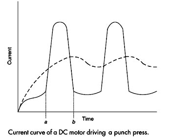
Sir DC machine ka yeah questions SSC je solved 2018-19 options me nehi dikh Raha hai