Ques.61. The emf induced in a DC shunt generator is 230 V. The armature resistance is 0.1Ω. If the armature current is 200 A, the terminal voltage will be (SSC-2014)
200V
230V
210 V
250 V
Answer.3. 210 V
Explanation:-
Terminal voltage of DC shunt generator is
V = E – IaRa
Where E is generated EMFI
Ia is armature current
Ra Armature resistance
V = 230 – 0.1 x 200
V = 230 – 20
V = 210 V
Ques.62. The commutator of a DC generator acts as, (SSC-2014)
An amplifier
A rectifier
A load
A multiplier
Answer.2. A rectifier
Explanation:-
The commutator is a mechanical rectifier, so the commutator collects induced EMF or current developed in the armature.
The commutator converts the alternating current generated in armature into the unidirectional current.
Ques.63. Fleming’s left-hand rule is applicable to (SSC-2014)
DC generator
DC motor
Alternator
Transformer
Answer.2. DC motor
Explanation:-
Fleming’s left-hand rule is applicable to DC motor because the direction of rotation of motor or direction of force experienced i.e motoring action can be determined by Fleming’s left-hand rule
Ques.64. The load characteristics of dc shunt generator are determined by (SSC-2013)
The voltage drop in armature resistance
The voltage drop due to armature reaction, the voltage drop due to decreased field current and voltage drop in armature resistance
The voltage drop due to armature reaction and voltage drop in an armature resistance
The voltage drop due to the armature reaction, the voltage drop due to decreased field current and voltage drop in armature resistance and field resistance.
Answer.2. The voltage drop due to armature reaction, the voltage drop due to decreased field current and voltage drop in armature resistance
Explanation:
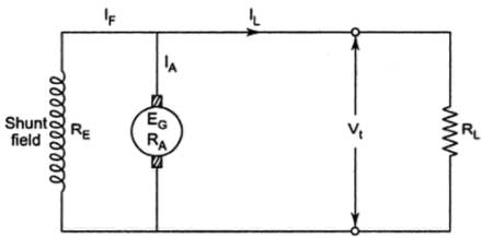
DC Shunt Generator
The above figure shows the circuit diagram of DC shunt generator where
IA = Armature current
IL = Load current
IF = Field current
RA = Armature Resistance
In the shunt generator, the field winding is connected parallel to the armature winding. When the load is connected across the armature, then there exists a voltage drop in field as well as armature winding. The voltage drop appears to IaRa armature reaction and weakened flux.
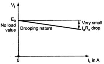
load characteristics of DC Shunt Generator
The load characteristics of DC shunt generator are also called the external characteristics and It will only be slightly shifted from the internal characteristic as IL = Ia — If where If (field current) is usually very small.
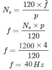
Ques.65. A 4-pole generator is running at 1200 rpm the frequency and time period of E.M.F generated in its coils are respectively. (SSC-2013)
50 Hz & 0.02 sec
40 Hz & 0.025 sec
300 Hz & 0.0033 sec
2400 Hz & 0.0260 sec
Answer.2. 40 Hz & 0.025 sec
Explanation:
f = 1/ t
t = 1 /40
= 0.025 sec
Ques.66. If the supply polarity to the armature terminal of a separately excited d.c.motor is reversed, the motor will run under (SSC-2013)
Plugging condition
Regenerative braking condition
Dynamic breaking condition
Normal motoring condition
Answer.1. Plugging condition
Explanation:
Plugging in DC Motor
Plugging of Dc motor is the method of reconnecting the motor to the line with reverse polarity hence now the motor will produce torque in the opposite direction to that of rotation.
Plugging in DC motor means the reversing of either field or armature current. So either Eb or V gets reversed. Therefore, the voltage across the armature will be V+Eb which is almost twice the supply voltage.
The rotor speed decreases until it becomes zero and then the rotor accelerates in the opposite direction. Therefore, the plugging is used to get a quick reversal and a rapid stop or Braking.
Ques 67. A dc series motor has an armature resistance of 0.06 Ω and a series field resistance of 0.08 Ω. The motor is connected to a 400 V supply. The line current is 20 A when the speed of the machine is 1100 rpm. When the line current is 50 A and the excitation is increased to 30%, the speed of the machine in rpm is (SSC-2013)
1100 RPM
1003 RPM
837 RPM
938 RPM
Answer.3. 837 RPM
Explanation:
Here
V = 400 V , I1 = 20 A, N1 = 1100
Ra = 0.06 ohm, Rse = 0.08 ohm
I2 = 50 A, N2 =?
Φ2 = 130 % of Φ1 = 1.3 Φ1
While drawing line current of 20 A
Eb1 = V – I1(Ra + Rse)
= 400 – 20(0.06 + 0.08)
= 397. 2 V
While drawing line current of 50 A
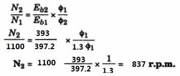
Eb2 = V – I2(Ra + Rse)
= 400 – 50(0.06 + 0.08)
= 393 V
We know that
Ques.68. The commutator in a dc machine acts as (SSC-2013)
A mechanical inverter
A mechanical rectifier
Current controller
Either (A) or (B)
Answer.4. Either (A) or (B)
Explanation:
The commutator is a mechanical rectifier, so the commutator collects induced EMF or current developed in the armature.
In a motor, the commutator applies electric current to the windings. By reversing the current direction in the rotating windings each half turn, a steady rotating force (torque) is produced.
Therefore commutator work as the mechanical rectifier and current controller.
Ques.69. The purpose of using the dummy coil in a dc machine is to (SSC-2013)
Eliminate harmonics developed in the machine
Eliminate armature reaction
Bring mechanical balance of the armature
Bring mechanical balance of the body of the motor
Answer.3. Bring mechanical balance of the armature
Explanation:
Dummy coil is used with wave winding when the requirement of the winding is not met by the standard armature.
Dummy coil is not connected to the commutator so they do not influence the electrical characteristics of the winding
Dummy coil ends are cut short and taped.
Their main use is to provide mechanical balance for the rotor because the rotor having some slots without winding would be out of balance mechanically.
Ques.70. For a 6-pole dc machine with wave wound armature, the number of brushes required is (SSC-2013)
2
4
6
12
Answer.1. 2
Explanation:
In wave winding the number of brushes is always 2 irrespective of the number of poles

Sir DC machine ka yeah questions SSC je solved 2018-19 options me nehi dikh Raha hai