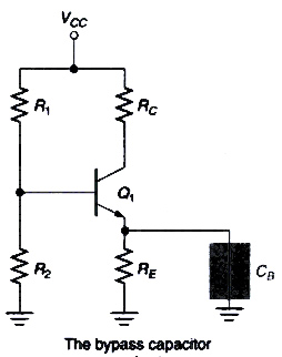
Ques.21. The purpose of the emitter bypass capacitor in a CE BJT amplifier is to
Prevent saturation of the amplifier
Place the Q-point of the transistor in the active region
Provide a stable biasing for the amplifier
Increase the mid-band voltage gain of the amplifier
Answer.4. Increase the mid-band voltage gain of the amplifier
Explanation:-
A bypass capacitor is a capacitor that is used to establish an ac ground (or common) connection at a .specific point in a circuit. The voltage gain of a common-emitter amplifier varies inversely with its total ac emitter resistance. The lower the ac resistance of the emitter circuit, the greater the voltage gain of the amplifier. By effectively shorting RE. the bypass capacitor ensures that the value of RE does not weigh into the voltage gain calculation for the amplifier.
The bypass capacitor also provides a low reactance path to the amplified a.c. signal. If it is not inserted, the amplified a.c. signal passing through RE will cause a voltage drop across it. This will reduce the output voltage, reducing the gain of the amplifier.
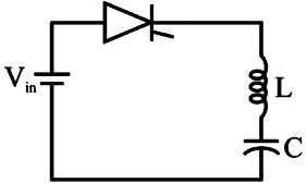
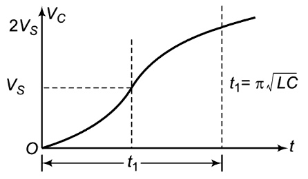
Ques.22. The SCR in the circuit is turned on at t = 0. The conduction time duration of the SCR is
[katex]2\pi \sqrt {LC}[/katex]
[katex]\pi \sqrt {LC}[/katex]
[katex]\sqrt {LC}[/katex]
[katex]1/2\pi \sqrt {LC}[/katex]
Answer.2. [katex]\pi \sqrt {LC}[/katex]
Explanation:-
The conduction time of thyristor in one complete cycle for LC Load is
[katex]u\left[ n \right] = \left. {\left\{ \begin{array}{l}1,if{\text{ n}} \ge {\text{0}}\\1,if{\text{ n}} \le {\text{0}}\end{array} \right.{\text{ for n = \{ – }}\infty …. – 1,0,1….\infty \} } \right\}[/katex]
The z- transform of u{n} is U (z). The region of convergence for which the z-transform of u[n] exists is
|z| > 1
|z| < 1
|z| = 1
|z| > 0
Answer.1. |z| > 1
Explanation:-
The z transform of unit step sequence u(n) is given by u(z)
[katex]u(z) = \dfrac{1}{{1 – {Z^{ – 1}}}}[/katex]
Because u(z) transform has a zero at |z| = 0 and a pole at |z| = 1, hence the region of convergence is
|z| > 1
Ques.24. The graph of an electrical network has N nodes and B branches. The number of links, L, for any tree spanning all nodes is given by
B + N
N − B + 1
N − 2B + 1
B − N + 1
Answer.4. B − N + 1
Explanation:-
Number of Node = N
Number of branch = B
Number of tree branches (twig) = (N − 1)
Number of Link = (Total number of branches) − (Number of twig)
L = (B) − (N − 1)
L = B − N + 1
Ques.25. A single-phase power transformer is to be energized (switched on to the input supply) to have minimum inrush current. The switching-on Instant should be at
Zero input voltage
1/2 of the maximum input voltage
Maximum Input voltage
1/√2 of the maximum input voltage
Answer.3. Maximum Input voltage
Explanation:-
When energized, a transformer draws an inrush current. Therefore, when a generator is connected to a system containing transformers, the transformers will try to draw an inrush current from the generator. Apart from other factors the magnitude of the anent also depends on the short circuit capacity and the voltage of the source. Because of this, a low-voltage generator cannot supply a large inrush current like a high-voltage generator. Therefore, a single set can energize many transformers or a whole system (on no load). A high-voltage set will supply more inrush current.
When the input voltage is maximum, the rate of change of flux is minimum; as both are 90° out of the phase-in case of sinusoidal input.
If we close the switch at the instant of zero value of supply voltage, the flux demanded by the core is maximum and inrush current is also maximum.
Ques.26. Consider the following Laplace transforms of certain signals. For which of the following. final value theorem is not applicable?
(S − 1)/(S + 2)
(S + 1)/(S + 2)
(S + 1)/(S + 2)(S + 3)
(S + 1)/(S – 2)
Answer.4. (S + 1)/(S – 2)
Explanation:-
The final value theorem applies only if all the poles of X(s) are in the left half of the s-plane, with almost a single pole at s = 0.
From the given above option (S + 1)/(S – 2) is unstable as its poles lies on the right half of s-plane therefore the final value theorem can not be applied.
Ques.27. Consider a signal g(t), such that g(t) = 0 for t < 0. If the Laplace transform of g(t) is G(s), then with constant τ, the Laplace transform of g(t − τ) is
G(s + τ)
esτ G(sτ)
e−sτ G(s)
G(s − τ)
Answer.1. e−sτ G(s)
Explanation:-
The time shifting property of Laplace transformation is given by expression
L{X(t − τ)} = e−st X(t)
The unilateral Laplace transform of g(t − τ) will be
L{g(t − τ)} = e−st G(s)
Ques.28. A Buchholz relay is used for
Protection of a transformer against internal and external faults
Protection of a transformer against internal faults
Protection of a transformer against external faults
None of the options is correct
Answer.2. Protection of a transformer against internal faults
Explanation:-
Buchholz relay is a gas actuated relay. This relay is used to detect incipient faults and protect the transformer. If minor faults are not detected in time, they may develop into a major fault in course of time. Buchholz relay is a very simple relay for the protection of the transformer against internal faults.
Whenever a fault occurs, sparking takes place and the heat generated thereby decomposes the transformer oil into hydrogen and hydrocarbon gases. These gases being very light push the oil downward and rise upward and they get collected at the top. The gas formation is used to protect the transformer.
Ques.29. Two inductors of 5 H and 4 H have a mutual inductance of 2.5 H between them. The coupling coefficient is
Ques.30. To ensure successful turn-on of a thyristor, the minimum gate pulse width of the thyristor gate pulse should be sufficient to ensure the cathode current to reach
The holding value of thyristor current
The peak value of thyristor current
The latching value of thyristor current
50% of the peak value of thyristor current
Answer.3. The latching value of thyristor current
Explanation:-
When the SCR is triggered, gate current is not required for SCR to remain in the ON state. If the gate current is removed, the conduction of current from anode to cathode is unaffected. However, if the gate current is reduced to zero before anode current attains a value called latching current, SCR will turn OFF again.
Latching current is defined as the minimum value of anode current, that to be attained during the turn-on process, to maintain conduction when the gate signal is removed.
SCR can be turned OFF by reducing anode current below a value called holding current. Holding current is defined as the minimum value of anode current below which SCR will cease to conduct.