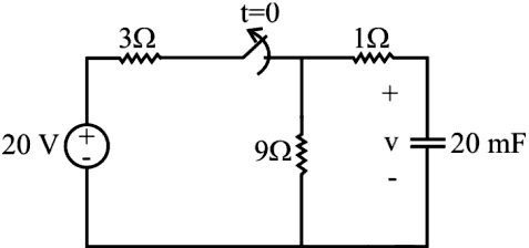
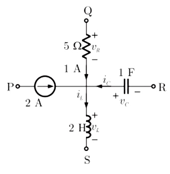
Ques.51. The switch in the circuit has been closed for a long time, and it is opened at time t=0. Find v(t) for t ≥ 0.
V(t) = 15e−5t V
V(t) = 15 V
V(t) = o V
V(t) = 15e−20t V
Answer.1. V(t) = 15e−5t V
Explanation:-
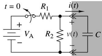
The switch in the Figure has been closed for a long time and is opened at t = 0. We want to find the capacitor voltage v(t) for t ≥ 0.
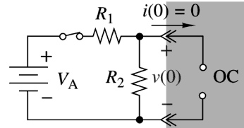
STEP 1:- The initial condition is found by dc analysis of the circuit configuration in Figure, where the switch is closed. Using the voltage division, the initial capacitor voltage is found to be
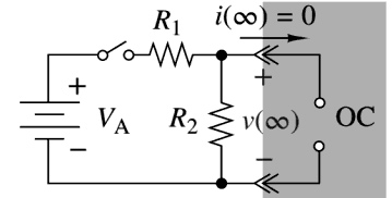
STEP 2:- The final condition is found by dc analysis of the circuit configuration in Figure where the switch is open. When the switch is open the circuit has no dc excitation, so the final value of the capacitor voltage is zero.
STEP 3:- The circuit in the figure also gives us the time constant. There is an equivalent resistance of (9Ω + 1Ω), since R1 is connected in series with an open switch. For t ≥ 0 the time constant is τ. Thus the capacitor voltage for t ≥ 0 is
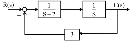
As seen from the closed loop transfer function, there is no pole at origin therefore the type of the system is zero.
Ques.54. The positive value K of will have K for zeroes which [katex]\left[ {1 + \dfrac{K}{{(s + 1)(s + 2)}}} \right][/katex] on the right-half of the complex s-plane is
20
0.1
10
No such K exists
Answer.4. No such K exists
Explanation:-
Applying Routh-Hurwitz criterion
(s + 1)(s + 2) + K = 0
s2 + 3s + (2 + K) = 0
For K > 0, no such value exists so that zeros lies in the right half of the s-plane.
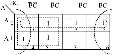
Ques.55. A combination circuit is described by a function as the sum of min-terms. The function is defined as f (A,B,C) = Σm(0,1, 2, 3, 4, 5, 6) A is the MSB and C is the LSB. The minimized expression of the function is
ABC
[katex]\overline B + \overline C[/katex]
[katex]\overline A + \overline B+C[/katex]
[katex]\overline A + \overline B+\overline C [/katex]
Answer.4. [katex]\overline A + \overline B+\overline C [/katex]
Explanation:-
Solving the K-map
There is three-Quads, so the Minimized expression of the function is
[katex]\overline A + \overline B+\overline C [/katex]
Ques.56. A current of −8 + 6√2 (sinωt + 30°) A is passed through three meters. These are a zero centered PMMC meter, a true RMS meter, and a moving iron instrument. The respective readings (in A) will be
8, 6, 10
−8, 6, 10
8, 6, 8
−8, 10, 10
Answer.4. −8,10,10
Explanation:-
⇒ PMMC reads only DC value
A waveform that consists of both DC & AC components can be represented as
Ao + A(sinωt + φ)
Where
Ao = DC Component
A(sinωt + φ) = AC component (instantaneous value & A is peak value)
Since PMMC reads only DC value
PMMC Reading = −8 A
Moving iron meter and RMS meter reads RMS value of current therefore
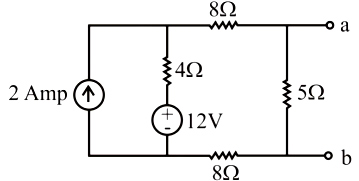
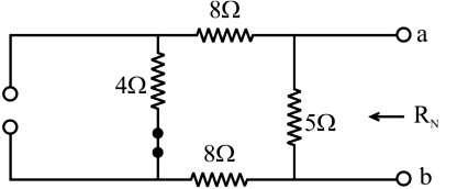
Ques.57. Find Norton equivalent resistance, RN, and equivalent current source, iN, at terminals a and b of the circuit.
RN = 5.33 Ω, iN = 0.71 A
RN = 4 Ω, iN = 1 A
RN = 12 Ω, iN = 0.71 A
RN = 5 Ω, iN = 2 A
Answer.2. RN = 4 Ω, iN = 1 A
Explanation:-
For Norton resistance, replace the sources with their internal resistance.
The voltage source is replaced by short-circuited and the current source is replaced by open-circuited.
Then finding the equivalent resistance across terminals ab
Resistance 8Ω, 4Ω & 8Ω are connected in series
R = (8 + 4 + 8) = 20Ω
Finally, 20Ω is parallel with 5Ω
Req = RN = Rth = 20||5
Req = (20 × 5)/(20 + 5)
Req = 4Ω
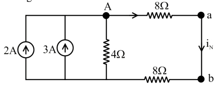
For finding the Norton current, a-b terminals are shorted and therefore the 5-ohm resistor is eliminated and converting voltage source into the current source.
Total current = 2A + 3 A = 5A
Applying the current divider rule
IN = (4 × 5)/(4 + 8 + 8)
IN = 1 A
Ques.58. A sequence u[n] is defined as
[katex]u\left[ n \right] = \left. {\left\{ \begin{array}{l}1,if{\text{ n}} \ge {\text{0}}\\1,if{\text{ n}} \le {\text{0}}\end{array} \right.{\text{ for n = \{ – }}\infty …. – 1,0,1….\infty \} } \right\}[/katex]
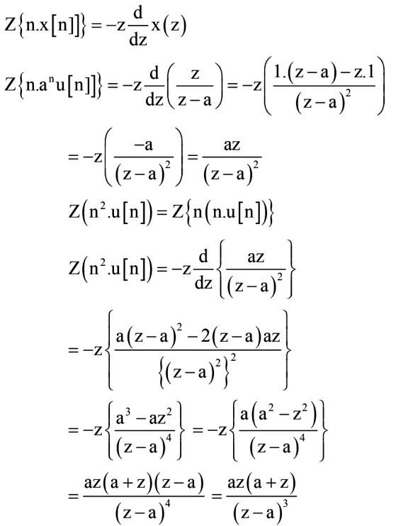
Consider a sequence x[n] = n2anu[n]. where a is a positive constant. The z-transform of the sequence with appropriate region of convergence is
az(z + a)/(z − a)3
z/(z − a)2
az/(z − a)2
ze−a/(z − e−a)2
Answer.1. az(z + a)/(z − a)3
Explanation:-
Given
[katex]u\left[ n \right] = \left. {\left\{ \begin{array}{l}1,if{\text{ n}} \ge {\text{0}}\\1,if{\text{ n}} \le {\text{0}}\end{array} \right.{\text{ for n = \{ – }}\infty …. – 1,0,1….\infty \} } \right\}[/katex]
Using the multiplication by n property of z-transform i.e.
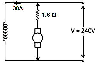
Ques.59. A 240 V DC shunt motor has an armature resistance of 0.6 Ω. The full load armature current is 30 A. The ratio of the stalling torque to the full load torque when the resistance of 1 Ω is connected in series with the armature is
3
5
6
4
Answer.2. 5
Explanation:-
Given
Ra = 0.6 Ω
Iafull = 30 A
VDC = 240 V
Now 1Ω resistance is connected in series with armature then total resistance become
Ra = 1 + 0.6 = 1.6 Ω
During Stalling torque or the breakdown torque, the speed falls to zero